Ventricle assisting device implanted through interventional micro-injury operation
A ventricular assist device and minimally invasive intervention technology, applied in heart valve, medical science, prosthesis and other directions, can solve the problems of difficult operation, large cardiac trauma, limited adaptability, etc., to overcome design defects, strong mobility, Good dispersion effect
- Summary
- Abstract
- Description
- Claims
- Application Information
AI Technical Summary
Problems solved by technology
Method used
Image
Examples
Embodiment 1
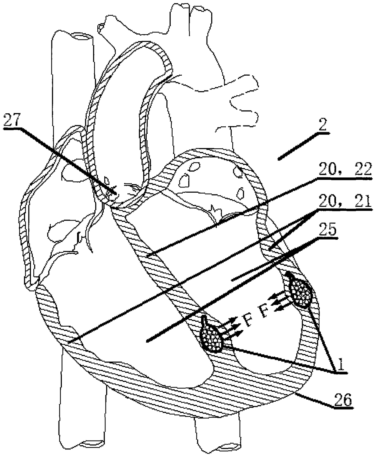
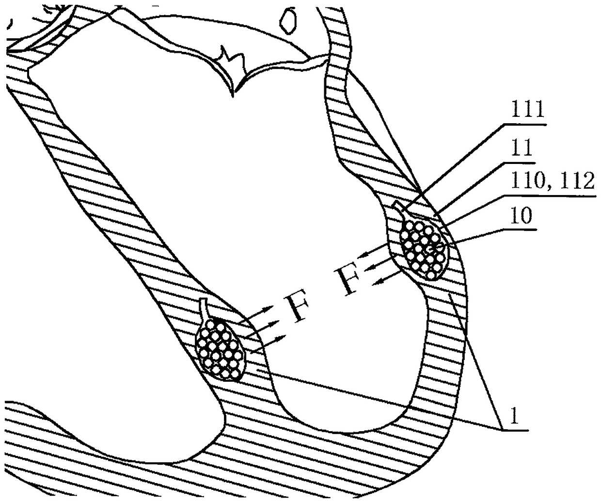
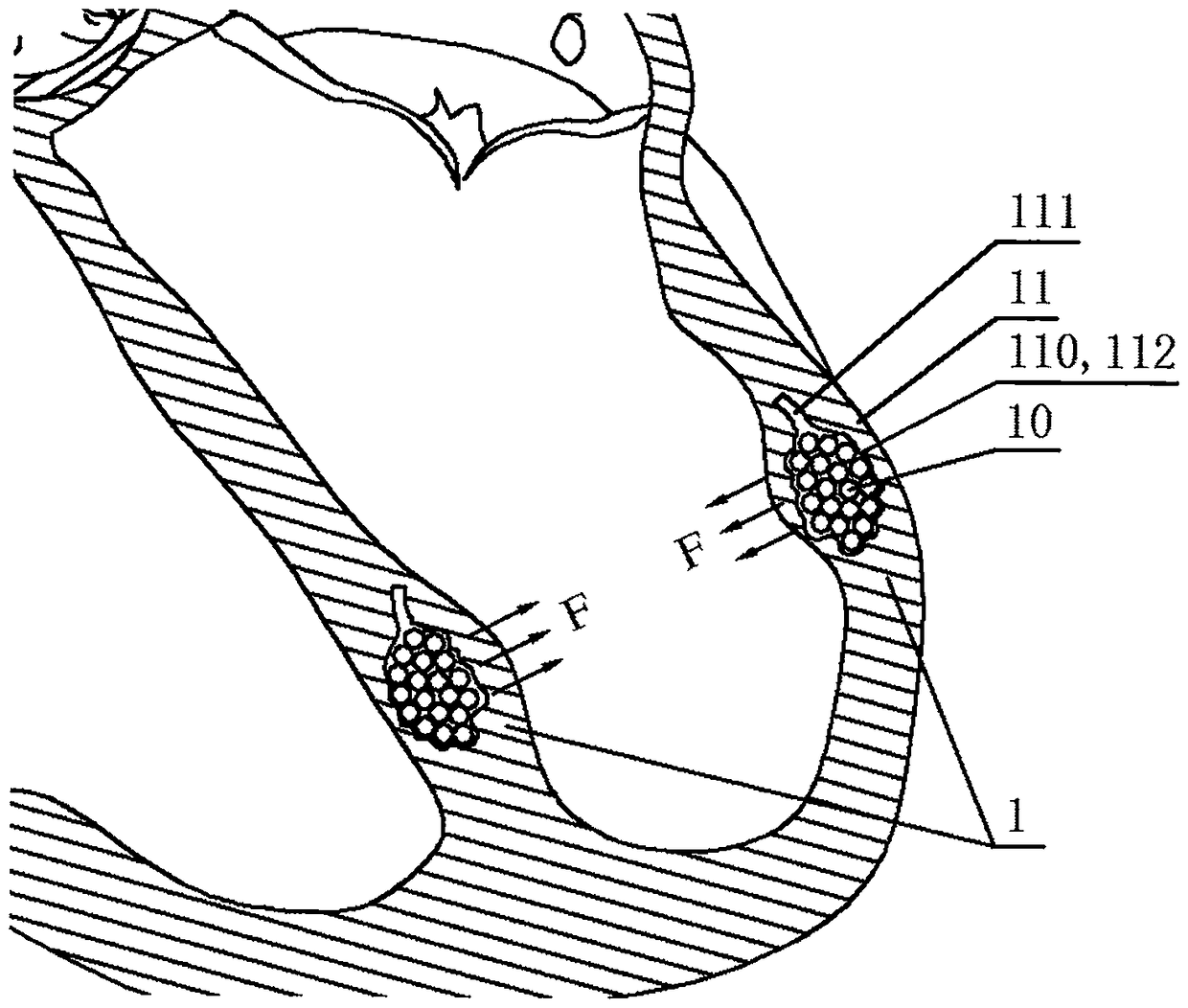
[0051] The ventricular assist device that can be implanted through minimally invasive intervention (hereinafter referred to as “the device”) provided by the present invention includes two magnetic components 1 that can attract each other, at least a part of the magnetic component 1 is located in the heart wall 20 . Two magnetic assemblies 1 that attract each other generate a mutual attractive force F. When the heart contracts, the force F exerts a pulling force or pressure on the heart tissue that is in direct contact with the magnetic assembly 1, including the heart wall 20, toward the inside of the heart. The distance between the cardiac tissue in direct contact with or surrounding the two magnetic components 1 can be reduced to drive the entire heart to contract, so the two magnetic components 1 can play a role in assisting the contraction of the heart, and finally increase the cardiac output per stroke. increase, thereby improving heart failure symptoms. Such as Figure 1...
Embodiment 2
[0068] Based on the first embodiment, the difference between the second embodiment and the first embodiment is that a restricting mechanism 1110 is provided inside the storage element 11 to restrict the magnetic element 10 in the storage element 11 and prevent the magnetic element 10 from leaking. In one embodiment, the restriction mechanism 1110 is a one-way valve with only one-way flow performance, such as Figure 6a with Figure 6b As shown, this one-way valve can make the magnetic element 10 easily enter the storage body 110 from the storage opening 111, but can prevent the magnetic element 10 from leaking from the storage opening 111 to the outside of the storage component 11, thus further improving the safety of the device. safety. In another embodiment, the restricting mechanism 1110 has a structure that can reduce the size of the inner cavity of the receiving mouth 111, such as a combination of tightening wire 1111 and tightening track 1112, such as Figure 6c As sho...
Embodiment 3
[0070] Based on the first embodiment, the first difference between the third embodiment and the first embodiment is that the storage element 11 includes two or more storage bodies 110, and one or more storage ports fixedly connected with the storage bodies 110 part 111, a storage connection part 1100 is further provided between the storage main body 110, Figure 7a with Figure 7c It is respectively shown that two spherical or cuboid storage bodies 110 are fixedly connected through the storage connection part 1100 . For the magnetic component 1 formed by injecting and filling the magnetic component 10 into the storage component 11 described in this embodiment, a neck can be formed at the storage connection part 1100. When the neck is located in the heart wall 20, the magnetic component can be used 1 The final form of its own makes the magnetic assembly 1 and the heart wall 20 relatively fixed, such as Figure 7b with 7d As shown, the long-term effectiveness of the fixation ...
PUM
 Abstract
Description
Claims
Application Information
 - R&D
- Intellectual Property
- Life Sciences
- Materials
- Tech Scout
- Unparalleled Data Quality
- Higher Quality Content
- 60% Fewer Hallucinations
Browse by: Latest US Patents, China's latest patents, Technical Efficacy Thesaurus, Application Domain, Technology Topic, Popular Technical Reports.
© 2025 PatSnap. All rights reserved.Legal|Privacy policy|Modern Slavery Act Transparency Statement|Sitemap|About US| Contact US: help@patsnap.com


