Machining device for milling cutters

A processing device and milling cutter technology, applied in the field of milling machine parts processing, can solve problems such as reducing work efficiency

Inactive Publication Date: 2018-06-08
重庆臣凿科技有限公司
View PDF0 Cites 0 Cited by
  • Summary
  • Abstract
  • Description
  • Claims
  • Application Information

AI Technical Summary

Problems solved by technology

Among them, the steps of cylindrical grinding, outer diameter grinding and deburring of coarse steel all need to grind the milling cutter in the process, and the existing milling cutter grinding device can only grind and process the milling cutter with a specific diameter. When processing milling cutters with different diameters, it is necessary to replace the corresponding grinding wheels, which reduces the work efficiency

Method used


Image

  • Machining device for milling cutters
  • Machining device for milling cutters
  • Machining device for milling cutters

Examples


Embodiment Construction

[0016] The following is further described in detail by specific embodiments:

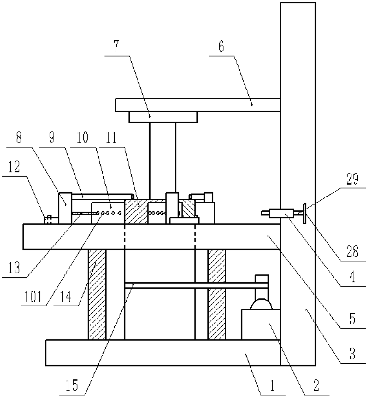
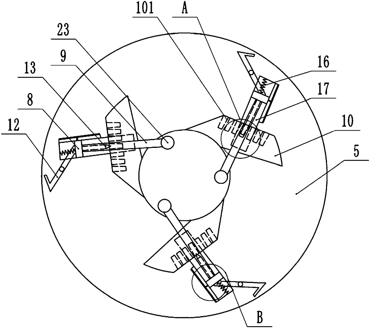
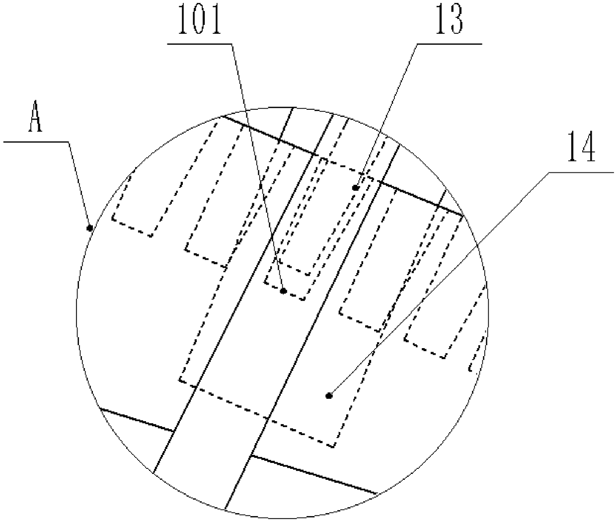
[0017] The reference signs in the accompanying drawings include: base 1, motor 2, slide rail 3, fixed tube 4, rotating plate 5, transverse plate 6, chuck 7, baffle 8, grinding rod 9, blade 10, top tightening hole 101. Grinding wheel 11, toggle rod 12, jacking rod 13, support rod 14, belt 15, spring 16, groove 17, grinding ball 23, scale 26, pointer 27, adjusting disc 28, pressing rod 29.

[0018] The example is basically as attached Figure 1-Figure 4 Shown: a milling cutter processing device, comprising a base 1 and a vertical slide rail 3, the bottom end of the slide rail 3 is welded on the base 1, the base 1 is provided with two vertical support rods 14, the support rod 14 A rotating disc 5 is slidably connected to the top of the rotating disc 5, a perforation is provided in the middle of the rotating disc 5, a grinding wheel 11 is rotatably connected in the perforation, a motor 2 is provided on...


PUM


Abstract

The invention relates to a machining device for milling cutters. The device comprises a base and a vertical sliding rail, the bottom of the sliding rail is connected to the base, and supporting rods are arranged on the base; a rotation disc is slidingly connected to the tops of the supporting rods, a polishing wheel is rotatably connected to the rotation disc, and a through hole is formed in the middle of the polishing wheel; arc blades are connected to the outer wall of the polishing wheel, multiple abutting holes are formed in the sides, away from the polishing wheel, of the blades, and grooves are formed in the rotation disc; baffles are slidingly connected into the grooves, springs are connected between the sides, away from the blades, of the baffles and the groove walls of the grooves, and abutting rods for abutting against the interiors of the abutting holes are fixedly connected to the sides, close to the blades, of the baffles; polishing rods are arranged on the baffles, polishing balls which are opposite to the through hole are fixedly connected to the ends, away from the baffles, of the polishing rods, and stirring rods are rotatably connected to the rotation disc; one end of each stirring rod is fixedly connected with the corresponding baffle, a horizontal plate is slidingly connected to the sliding rail, and a clamping disc is fixedly connected to the side, facing the through hole, of the horizontal plate. According to the scheme, the milling cutters with different diameters are ground.

Description

technical field [0001] The invention relates to the technical field of milling machine parts processing, in particular to a milling cutter processing device. Background technique [0002] A milling cutter is a rotary tool with one or more teeth for milling. The milling cutter is usually cylindrical, and the manufacturing process of the milling cutter is divided into several steps, including the cylindrical grinding of the rough steel, the heat treatment of the billet, pickling, the billet rolling groove, the outer diameter grinding and deburring, annealing, opening. Blade, fine grinding, oiling, etc. Among them, the outer cylindrical grinding, outer diameter grinding and deburring of coarse steel all need to grind the milling cutter during the processing, and the existing milling cutter grinding device can only grind milling cutters with a specific diameter. When machining milling cutters of different diameters, it is necessary to replace the corresponding grinding wheel, ...

Claims


Application Information

Patent Timeline
IPC IPC(8): B24B3/02B24B41/06B24B41/02
CPCB24B3/02B24B41/02B24B41/06
Inventor 欧番
Owner 重庆臣凿科技有限公司
Why Eureka
Try Eureka