Treatment device for neodymium-iron-boron ultrafine powder waste material
A processing device and ultra-fine powder technology, which is applied in the field of NdFeB processing, can solve the problems of large contact area, high processing cost, and bursting, and achieve the effect of low processing cost, smooth discharge process, and not easy to block
- Summary
- Abstract
- Description
- Claims
- Application Information
AI Technical Summary
Problems solved by technology
Method used
Image
Examples
Embodiment 1
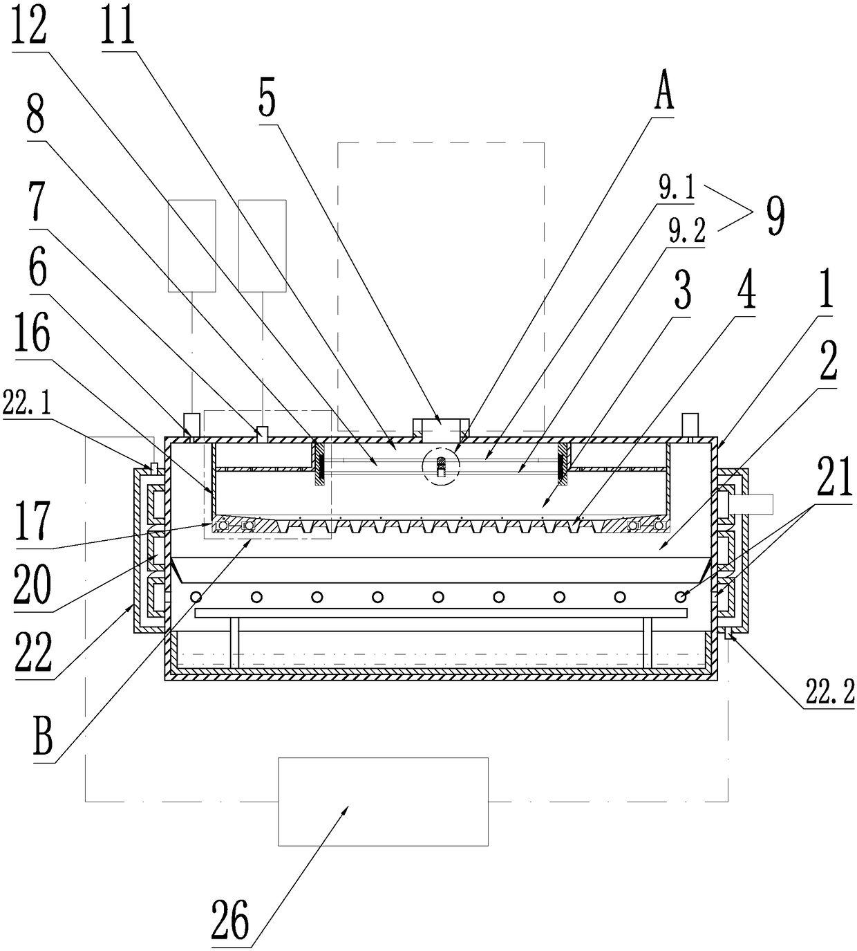
[0028]The support 8 has a cylindrical structure, the upper end surface of the support 8 is fixed and sealed with the inner surface of the furnace body 1, the blades 9 are rotatably fitted in the support 8, and the feeding port 5 is connected to the inner cavity of the support 8 by the inner surface of the support 8. Material cavity 3 communicates.
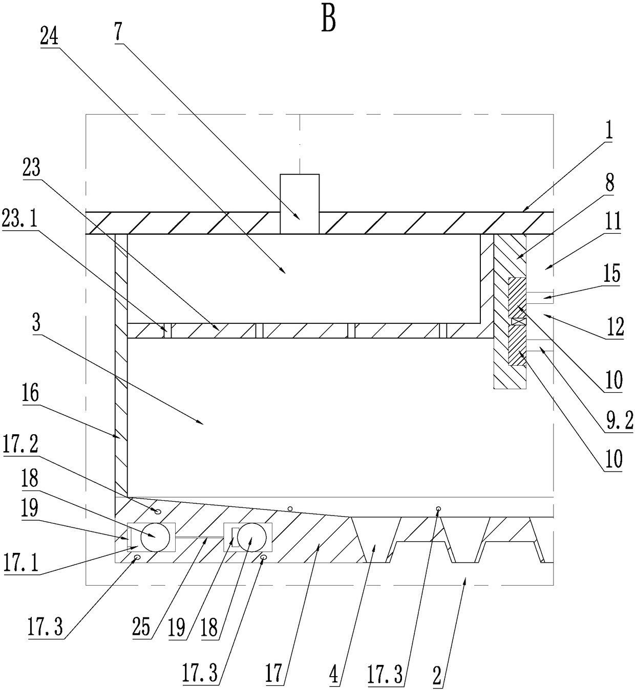
[0029] Further, a second bracket 23 is provided in the feeding chamber 3, and an annular pressure equalizing chamber 24 is formed between the second bracket 23 and the inner surface of the furnace. The second air inlet 7 on the furnace body 1 is connected to the equalizing The pressure chamber 24 is connected, and several air holes 23.1 communicating with the feeding chamber are arranged on the pressure equalization chamber, and all the air holes 23.1 are distributed along the circumferential direction of the pressure equalization chamber at intervals.
Embodiment 2
[0031] The motor 10 is a direct drive motor, the stator 10.1 of the motor 10 is fixedly connected with the support 8, the rotor 10.2 of the motor 10 is in rotation with the stator 10.1, and one end of the blade 9 is fixedly connected with the rotor 10.2.
[0032] Specifically, an annular mounting groove is radially recessed on the inner side wall of the bracket 8, and the stator 10.1 and the rotor 10.2 of the motor 10 are embedded in the mounting groove, and the rotor 10.2 is rotatably engaged with the mounting groove. In order to prevent the NdFeB superfine powder waste from falling into the motor, a sealing ring is provided between the rotor 10.2 and the inner wall of the installation groove.
Embodiment 3
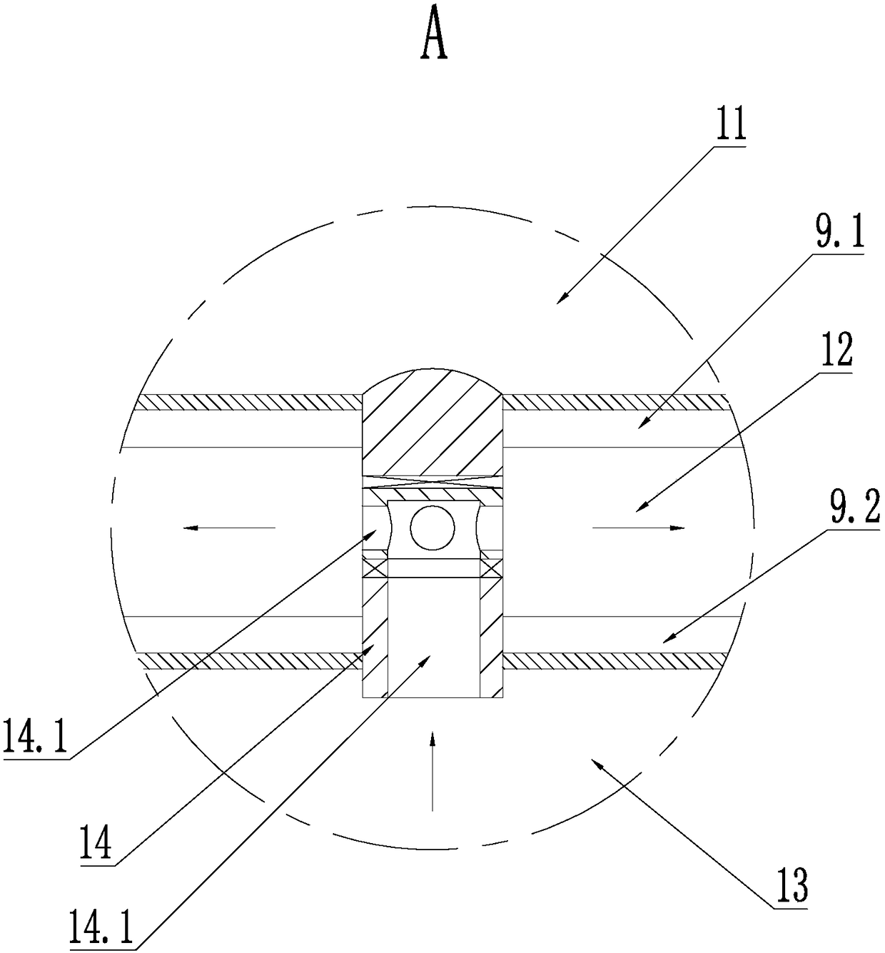
[0034] The blades 9 include an upper blade 9.1 and a lower blade 9.2 arranged vertically from top to bottom. From top to bottom, it is divided into a medium pressure zone 11, a low pressure zone 12 and a high pressure zone 13, that is, the area between the upper blade 9.1 and the feeding port 5 forms a medium pressure zone 11, and the upper blade 9.1 and the lower blade 9.2 form a low pressure zone 12 , the area below the lower blades 9.2 forms a high-pressure area communicated with the feed chamber 3 . The air pressures of the low-pressure zone 12, the medium-pressure zone 11 and the high-pressure zone 13 increase sequentially.
[0035] Specifically, the upper blade 9.1 rotates so that the air below the upper blade 9.1 is squeezed to the top of the upper blade 9.1, so a medium-pressure zone is formed above the upper blade 9.1, and a low-pressure zone 12 is formed between the upper blade 9.1 and the lower blade 9.2; The blade 9.2 rotates so that the air above the lower blade ...
PUM
 Abstract
Description
Claims
Application Information
 - R&D
- Intellectual Property
- Life Sciences
- Materials
- Tech Scout
- Unparalleled Data Quality
- Higher Quality Content
- 60% Fewer Hallucinations
Browse by: Latest US Patents, China's latest patents, Technical Efficacy Thesaurus, Application Domain, Technology Topic, Popular Technical Reports.
© 2025 PatSnap. All rights reserved.Legal|Privacy policy|Modern Slavery Act Transparency Statement|Sitemap|About US| Contact US: help@patsnap.com


