Magnetic control collision bumper

A buffer and magnetic control technology, which is applied in the direction of shock absorbers, shock absorbers, liquid shock absorbers, etc., to achieve the effects of optimizing buffer characteristics, improving operational reliability, and improving performance

Inactive Publication Date: 2018-06-08
CHONGQING UNIV OF TECH
View PDF7 Cites 3 Cited by
  • Summary
  • Abstract
  • Description
  • Claims
  • Application Information

AI Technical Summary

Problems solved by technology

Cylinder wall setting of liquid storage chamber ring working cylinder

Method used


Image

  • Magnetic control collision bumper
  • Magnetic control collision bumper

Examples


Embodiment Construction

[0020] In order to make the purpose, technical solutions and advantages of the present invention clearer, detailed embodiments are provided, and the present invention will be described in further detail below in conjunction with the accompanying drawings:

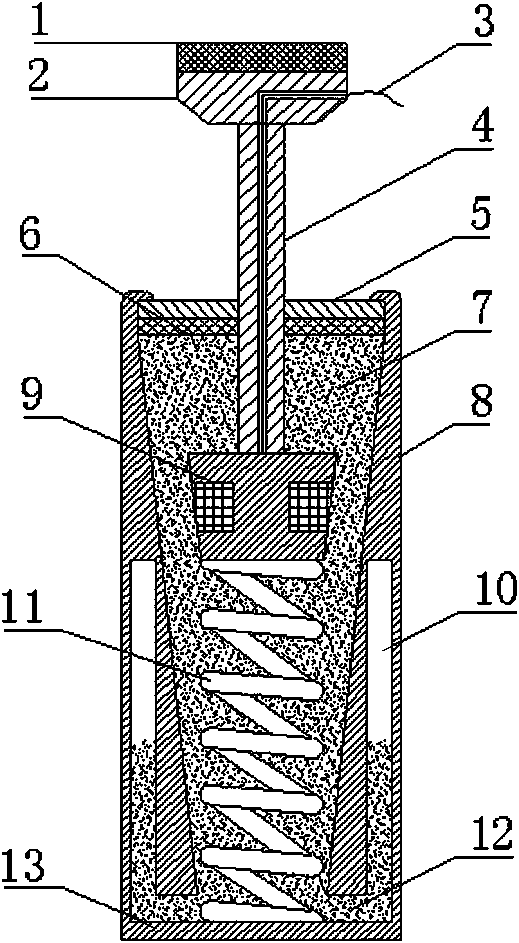
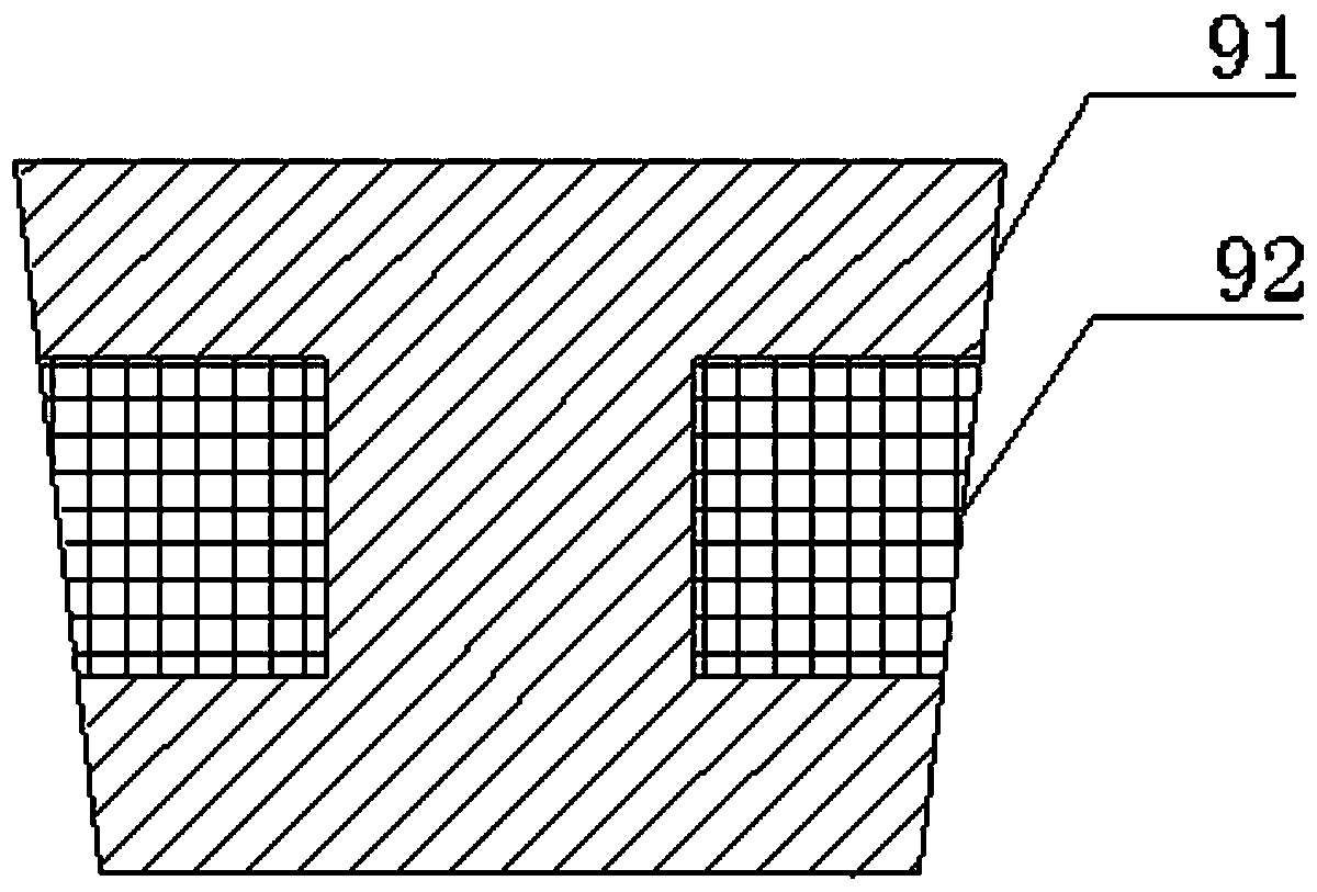
[0021] see figure 1 and figure 2 , this embodiment discloses a magnetically controlled collision buffer, including a working cylinder 8 and end covers 5 and bottom covers 13 located at both ends of the working cylinder 8 in the axial direction. The inner cavity of 8 is set to be large at the top and small at the bottom, so that the wall thickness of the cylinder wall of the working cylinder 8 gradually becomes thicker from top to bottom. The inner cavity of the working cylinder 8 is provided with a piston 9 and a spring 11, one end of the spring 11 is fixedly connected to the bottom of the piston 9, and the other end of the spring 11 is fixedly connected to the bottom cover 13 at the bottom of the working cylinder 8, so ...


PUM


Abstract

The invention discloses a magnetic control collision bumper. The magnetic control collision bumper comprises a working cylinder, an end cover and a bottom cover. A piston and a spring are arranged inthe working cylinder. One end of the spring is fixedly connected with the piston. The other end of the spring is fixedly connected with the bottom cover. The piston is fixedly connected with a pistonrod. The piston rod penetrates through the end cover, extends out of the working cylinder and then is fixedly connected with a collision head. The piston comprises a piston iron core and a magnet exciting coil. The magnet exciting coil is wound in a groove formed in the piston iron core. The two ends of the magnet exciting coil extend out of the bumper from through holes formed in the piston rod through leads. The axial cross section of the piston iron core is arranged in the shape of a big-end-up isosceles trapezoid. The outer wall of the piston iron core is parallel to the inner wall of theworking cylinder. A gap is formed between the outer wall of the piston iron core and the inner wall of the working cylinder. An annular liquid storage cavity is formed in the cylinder wall of the lower end of the working cylinder and communicates with an inner cavity of the working cylinder through a channel. The inner cavity of the working cylinder is filled with a magnetic control damping material. The damping parameters of the bumper can be adjusted by adjusting the intensity of an electromagnetic field, and the performance of the collision bumper is effectively improved.

Description

technical field [0001] The invention belongs to the technical field of buffers, and in particular relates to a magnetron collision buffer. Background technique [0002] Collision buffers are important parts of various mechanical equipment, and are necessary devices to absorb collision impact energy and alleviate unnecessary impacts, and have a wide range of engineering application value. Generally, the collision buffer has a working cylinder and a reciprocating piston rod. When the piston rod moves relative to the working cylinder in the axial direction, a damping force is generated that inhibits the movement of the piston rod relative to the working cylinder. Such a collision buffer is installed in vehicles, large-scale projects In machinery, the shock and collision effect can be greatly suppressed by the energy storage and damping characteristics of the shock absorber. At present, the most widely used collision buffer is the hydraulic buffer. Selecting the hydraulic buffe...

Claims


Application Information

Patent Timeline
Patent Type & Authority Applications(China)
IPC IPC(8): F16F9/19F16F9/32F16F9/53F16F9/36
CPCF16F9/19F16F9/3207F16F9/3214F16F9/368F16F9/535
Inventor 居本祥
Owner CHONGQING UNIV OF TECH
Why Eureka
Try Eureka