Checking method and checking data measurement apparatus of high-energy-beam additive-manufacturing finite-element thermal coupling model

A technology of additive manufacturing and thermomechanical coupling, applied in the field of additive manufacturing, can solve problems such as substrate deformation, cracking, and deformation of formed parts, and achieve the effect of multiple types of measurement data and comprehensive information

Active Publication Date: 2018-06-08
NORTHWESTERN POLYTECHNICAL UNIV
View PDF7 Cites 11 Cited by
  • Summary
  • Abstract
  • Description
  • Claims
  • Application Information

AI Technical Summary

Problems solved by technology

[0003] At present, there is no complete set of heat-deformation-strain in-situ real-time measurement device for the high-energy beam additive manufacturing process. The existing high-energy beam additive manufacturing in-situ measurement technology mainly measures the temperature and deformation of the substrate, and there are few In-situ real-time measurement of temperature and strain of formed parts
At present, most scholars use surface profilometers, laser 3D scanners and other means to obtain the final deformation of the substrate after the additive manufacturing process. This method can only measure the deformation of the substrate after processing, but cannot reveal Real-time deformation law of machined parts
Some schola...

Method used


Image

  • Checking method and checking data measurement apparatus of high-energy-beam additive-manufacturing finite-element thermal coupling model
  • Checking method and checking data measurement apparatus of high-energy-beam additive-manufacturing finite-element thermal coupling model
  • Checking method and checking data measurement apparatus of high-energy-beam additive-manufacturing finite-element thermal coupling model

Examples


Embodiment Construction

[0035] The present invention will be further described in detail below in conjunction with specific embodiments, which are explanations of the present invention rather than limitations.

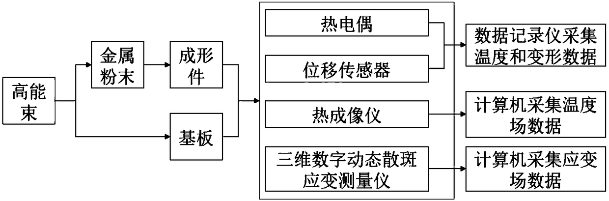
[0036] The invention relates to a method for verifying a finite element thermomechanical coupling model of high-energy beam additive manufacturing. The finite element thermomechanical coupling model is verified by using the heat-deformation-strain field measurement results obtained through real-time measurement by a data measuring device.

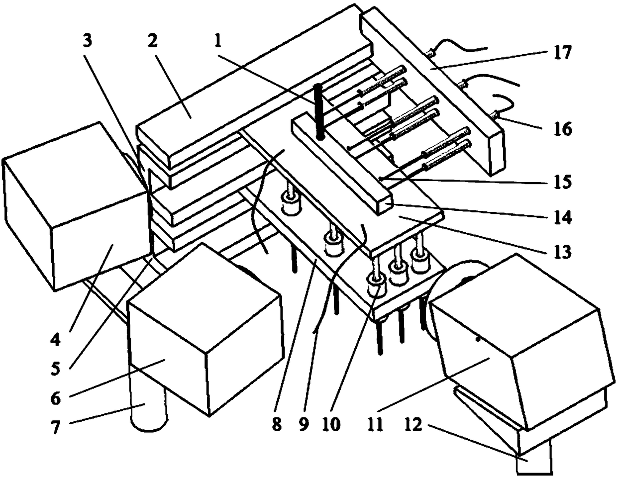
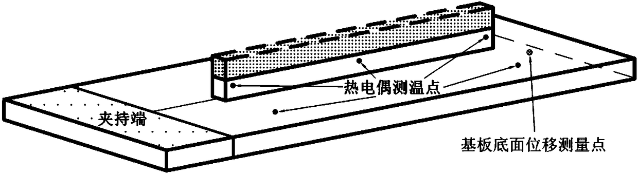
[0037] The following embodiments take the laser beam in the high-energy beam as a representative to illustrate how the present invention realizes the in-situ real-time accurate measurement of the heat-deformation-strain field by using the data measuring device in the high-energy beam additive manufacturing process and applies it to thermal-mechanical coupling Model validation. Such as figure 1 As shown, in the high energy beam processing process, the ther...


PUM


Abstract

The invention shows a checking method and checking data measurement apparatus of a high-energy-beam additive-manufacturing finite-element thermal coupling model. The apparatus comprises a workbench, afixture system and a data acquisition system, wherein the fixture system and the data acquisition system are installed on the workbench. In addition, the checking method includes: step one, carryingout real-time experiment measurement on a fusion covering process and heat-deformation-strain during high-energy-beam additive-manufacturing processing; step two, establishing a model framework, inputting a material property, and dividing a grid, and completing calibration of a finite-element temperature field; and step three, setting a force field boundary condition and using a calibrated temperature field results as an initial condition, obtaining a substrate deformation and strain field results, completing calibration of a finite-element force field, and thus completing calibration of a high-energy-beam additive-manufacturing finite-element thermal coupling model. According to the invention, reliable experiment data are provided for simulation of the high-energy-beam additive manufacturing; the scientific guidance is provided for establishing a process method for controlling deformation of the substrate and finished elements effectively; and thus application of the additive-manufacturing technology is prompted.

Description

technical field [0001] The invention relates to the field of additive manufacturing, in particular to a method for calibrating a finite element thermal-mechanical coupling model of high-energy beam additive manufacturing and a data measuring device thereof. Background technique [0002] High-energy beam additive manufacturing technology is a high-performance metal additive manufacturing technology developed based on the principle of rapid prototyping technology. It can be divided into two types: pre-powder powder and synchronous powder feeding or wire feeding. High-energy beams generally include plasma beams, electron beams, Laser beams and arcs etc. For high energy beam additive manufacturing simultaneous powder feeding or wire feeding technology, the formed parts are clad and formed on the prefabricated substrate. During the cladding process, the area near the molten pool is subjected to uneven rapid cooling and rapid heating, the molten pool solidifies and shrinks, the t...

Claims


Application Information

Patent Timeline
IPC IPC(8): G01D21/02G06F17/50
CPCG01D21/02G06F30/367
Inventor 林鑫鹿旭飞马良杨海欧谭华胡云龙
Owner NORTHWESTERN POLYTECHNICAL UNIV
Why Eureka
Try Eureka