
Fixed shaft type outer rotor brushless motor

A brushless motor, outer rotor technology, applied in synchronous motors with stationary armatures and rotating magnets, electrical components, electromechanical devices, etc., can solve problems such as increased power consumption, increased noise, and increased mechanical loss , to achieve the effect of extending service life, increasing reliability and reducing costs

Inactive Publication Date: 2018-06-08
东莞市卓奇电子科技有限公司
View PDF2 Cites 0 Cited by
  • Summary
  • Abstract
  • Description
  • Claims
  • Application Information

AI Technical Summary

Problems solved by technology

[0002] When the traditional turbine or fan blade rotates, it needs to rotate and drive with the output shaft of the motor. The output shaft of the motor belongs to the rotation center or reference center of the turbine or fan blade. When the output shaft of the motor rotates, the reference center is rotating. The strength, roundness, smoothness and concentricity of the output shaft of the motor have high requirements for machining accuracy; and with the change of working conditions, the output shaft of the motor is worn and deformed, which will cause vibration and noise of the load impeller, etc. Increase, mechanical loss increases, power consumption increases, damage is more severe, thus increasing the cost
In addition, when the traditional turbine or fan blade is connected to the output shaft of the motor, the output shaft can be directly inserted into the locking connection when the motor outputs low torque, but when the motor outputs high torque, the metal sleeve needs to be processed separately, and the Embedding injection molding when injection molding the impeller, this method further increases the cost of hardware inserts

Method used


Image

  • Fixed shaft type outer rotor brushless motor
  • Fixed shaft type outer rotor brushless motor
  • Fixed shaft type outer rotor brushless motor

Examples


Embodiment Construction

[0010] In order to describe the technical content, structural features, and achieved effects of the present invention in detail, the following will be described in detail in conjunction with the embodiments and accompanying drawings.

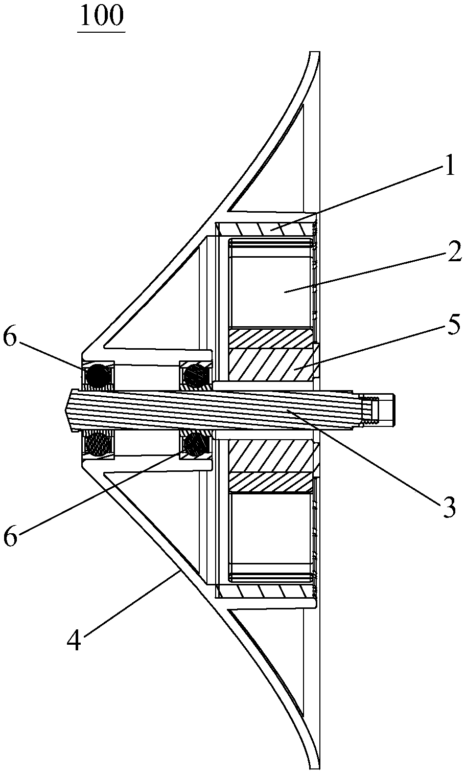
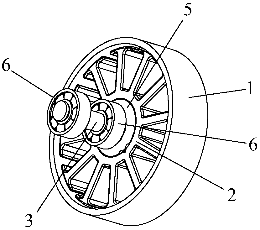
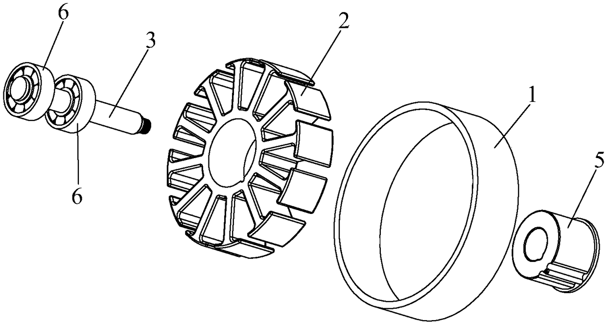
[0011] Such as figure 1 , figure 2 and image 3 As shown, the fixed shaft type outer rotor brushless motor 100 of the present invention includes a permanent magnet rotor 1, a winding stator 2, a fixed shaft 3 and a casing 4, the fixed shaft 3 is fixedly arranged, and the winding stator 2 is fixed on the On the fixed shaft 3, specifically, between the fixed shaft 3 and the winding stator 2, there is a fixing piece 5 for fixing the former two. The fixing piece 5 is in the shape of an annular sleeve, and the fixed shaft 3 is sleeved and fixed Inside the fixing part 5 , the winding stator 2 is sleeved on the outside of the fixing part 5 . Bearings 6 are provided between the fixed shaft 3 and the housing 4, and the number of the bearings 6 can be...


PUM


Abstract

The invention discloses a fixed shaft type outer rotor brushless motor, comprising a permanent magnet rotor, a winding stator, a fixed shaft and a shell. The fixed shaft is fixedly arranged. The winding stator is fixed to the fixed shaft. A bearing is arranged between the fixed shaft and the shell. The permanent magnet rotor is fixed to the inner wall of the shell, and surrounds the winding stator. The permanent magnet rotor drives the shell to rotate when rotating. By using the fixed shaft type outer rotor brushless motor, the requirement on the roundness, smoothness and concentricity of themotor output shaft can be reduced. Moreover, the fixed shaft type outer rotor brushless motor is of high reliability and lower cost.

Description

technical field [0001] The invention relates to a motor, in particular to a shaft-fixed outer rotor brushless motor. Background technique [0002] When the traditional turbine or fan blade rotates, it needs to rotate and drive with the output shaft of the motor. The output shaft of the motor belongs to the rotation center or reference center of the turbine or fan blade. When the output shaft of the motor rotates, the reference center is rotating. The strength, roundness, smoothness and concentricity of the output shaft of the motor have high requirements for machining accuracy; and with the change of working conditions, the output shaft of the motor is worn and deformed, which will cause vibration and noise of the load impeller, etc. Increase, mechanical loss increases, power consumption increases, damage is more severe, thus increasing the cost. In addition, when the traditional turbine or fan blade is connected to the output shaft of the motor, the output shaft can be dir...

Claims


Application Information

Patent Timeline
IPC IPC(8): H02K21/22H02K7/08
CPCH02K21/22H02K7/08
Inventor 谢奇峰
Owner 东莞市卓奇电子科技有限公司
Learn More