
A concrete photovoltaic roof support system

A photovoltaic support and support system technology, applied in the support structure of photovoltaic modules, photovoltaic power generation, photovoltaic modules, etc., can solve the problems of inconvenient installation and transportation, slow construction progress, cumbersome construction, etc., to achieve convenient installation and transportation, avoid safety hazards, Effect of increasing wind resistance

Active Publication Date: 2020-06-05
ZHEJIANG XINXIANG NEW ENERGY TECH CO LTD
View PDF2 Cites 0 Cited by
  • Summary
  • Abstract
  • Description
  • Claims
  • Application Information

AI Technical Summary

Problems solved by technology

The photovoltaic support in the prior art has a large amount of steel bars, heavy quality, high cost, inconvenient installation and transportation, large roof load, easy to damage the roof structure, great safety hazards, few applicable roofs, and poor adaptability; and the traditional steel support connection The method is cumbersome, the installation parts are many, the construction is cumbersome, the construction progress is slow, the wind resistance is weak, and it is easy to be damaged by bad weather such as rain, snow and wind, the maintenance and replacement costs are high, the use cost is high, the performance is unstable, the safety is poor, and waste resource

Method used


Image

  • A concrete photovoltaic roof support system
  • A concrete photovoltaic roof support system
  • A concrete photovoltaic roof support system

Examples


Embodiment Construction

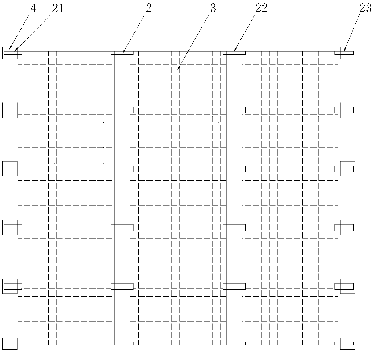
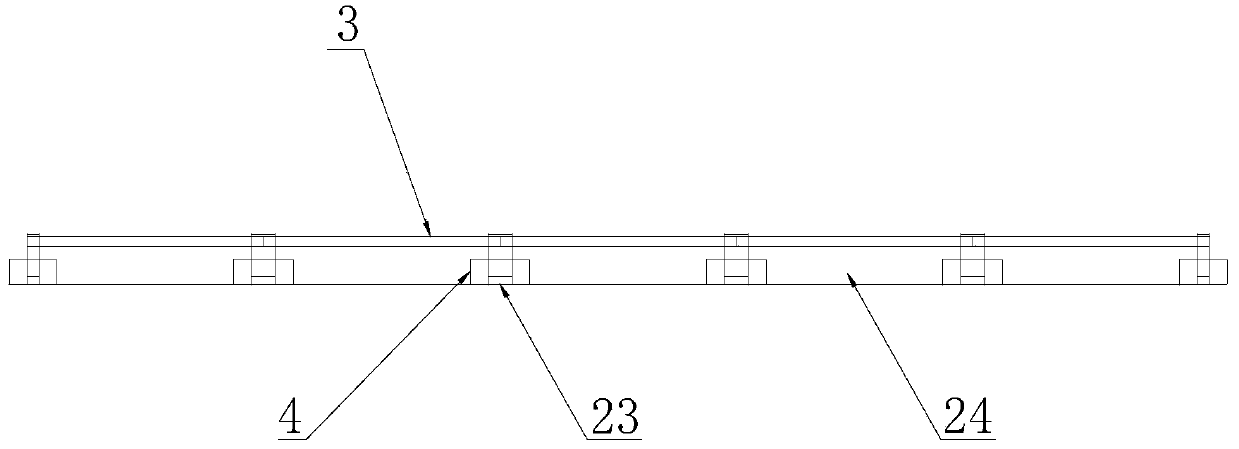
[0019] refer to Figure 1 to Figure 6 , a concrete photovoltaic roof support system of the present invention, including a base 1, a photovoltaic support 2, a photovoltaic module 3, a cement counterweight 4, self-tapping screws 5 and connectors 6, and the base 1 is provided with several photovoltaic supports 2 , the photovoltaic bracket 2 is provided with several self-tapping screws 5 and several connectors 6, the photovoltaic bracket 2 is installed and fixed on the base 1 through the self-tapping screws 5, and the two ends of the photovoltaic module 3 are connected through the connectors 6 is connected and fixed with the photovoltaic support 2. The photovoltaic assembly 3 forms an acute angle with the base 1 in the horizontal direction. The photovoltaic support 2 includes a first photovoltaic support 21, a second photovoltaic support 22 and a third photovoltaic support 23. The first A photovoltaic support 21 and a third photovoltaic support 23 are provided with cement counterw...


PUM


Abstract

The invention discloses a concrete photovoltaic roof support system. The concrete photovoltaic roof support system comprises a base, photovoltaic supports, photovoltaic modules, cement balancing weights, tapping screws and connection pieces, wherein the photovoltaic supports are fixedly arranged on the base by the tapping screws, two ends of the photovoltaic modules are connected and fixed with the photovoltaic supports via the connection pieces, acute angles are formed between the photovoltaic modules and the base in a horizontal direction, the cement balancing weights are arranged on a firstphotovoltaic support and a third photovoltaic support, and wind shielding plates are arranged on a second photovoltaic support and the third photovoltaic support. By connection of the photovoltaic supports and the photovoltaic modules in a matching way, the construction process is simplified, the construction cost is reduced, and the construction progress is accelerated; by employing high-strength plastic to substitute traditional metal, the production cost is greatly reduced, the weight of the whole support system is reduced, and the concrete photovoltaic roof support system is convenient toinstall and transport; the concrete balancing weights are utilized by calculating a load, the influence of air pressure of back air is reduced, and the roof bearing strain is reduced; and the wind shielding plates are arranged by tail parts of the modules, and the wind resistant performance of the support is improved.

Description

【Technical field】 [0001] The invention relates to the technical field of solar energy applications, in particular to the technical field of a concrete photovoltaic roof support system. 【Background technique】 [0002] The global energy crisis has promoted the rapid development of the new energy industry. Among many new energy sources, solar energy is favored by people as a low-cost, pollution-free, and renewable energy source. Therefore, solar energy that converts solar radiation into electrical energy Power generation technology, that is, the photovoltaic industry is developing rapidly. The photovoltaic support in the prior art has a large amount of steel bars, heavy quality, high cost, inconvenient installation and transportation, large roof load, easy to damage the roof structure, great safety hazards, few applicable roofs, and poor adaptability; and the traditional steel support connection The method is cumbersome, the installation parts are many, the construction is cum...

Claims


Application Information

Patent Timeline
Patent Type & Authority Patents(China)
IPC IPC(8): H02S20/23F24S20/67
CPCH02S20/23Y02B10/10Y02B10/20Y02E10/50
Inventor 陈国强翁迪龙李升张婷芳
Owner ZHEJIANG XINXIANG NEW ENERGY TECH CO LTD
Learn More