
Acoustic panel

A technology of sound insulation panels and microspheres, which is applied in construction, building components, building materials, etc., can solve problems such as the inability to use sound insulation panels and unsatisfactory light reflection of sound insulation panels, and achieve the effect of increasing costs

Pending Publication Date: 2018-06-08
ROCKWOOL AS
View PDF7 Cites 1 Cited by
  • Summary
  • Abstract
  • Description
  • Claims
  • Application Information

AI Technical Summary

Problems solved by technology

[0003] However, in some cases, it is not possible to use acoustic panels because the surfaces of current acoustic panels are less than ideal in terms of light reflection

Method used


Image

  • Acoustic panel
  • Acoustic panel
  • Acoustic panel

Examples


Embodiment Construction

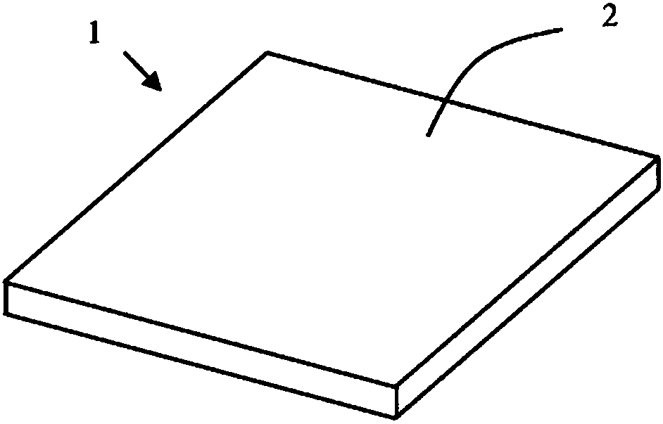
[0026] exist figure 1 A plate (1) with a first major surface (2) and an opposite second major surface can be seen in the schematic diagram of FIG. The first major surface (2) is provided with a facing such as non-woven or felt.

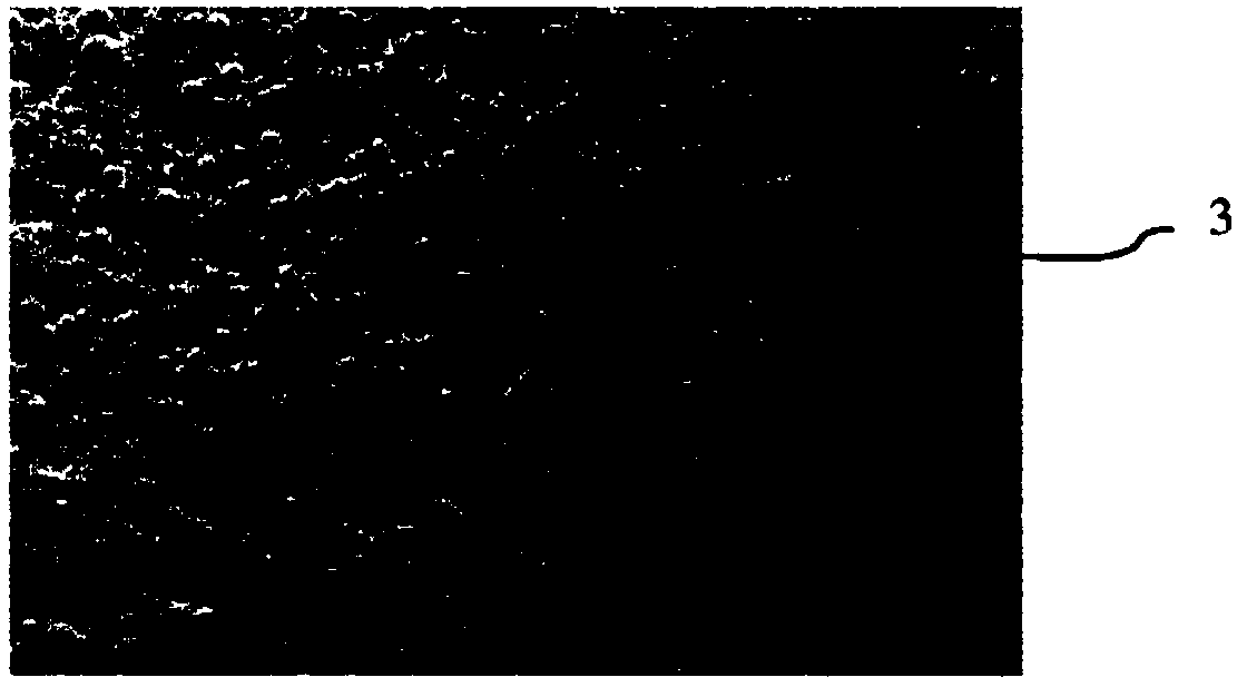
[0027] exist figure 2 Microspheres (3) in the coating can be seen in the close-up photo of . It can be seen that many microspheres are located in the surface, providing an optical effect and imparting high light reflectivity and robustness to the surface coating.

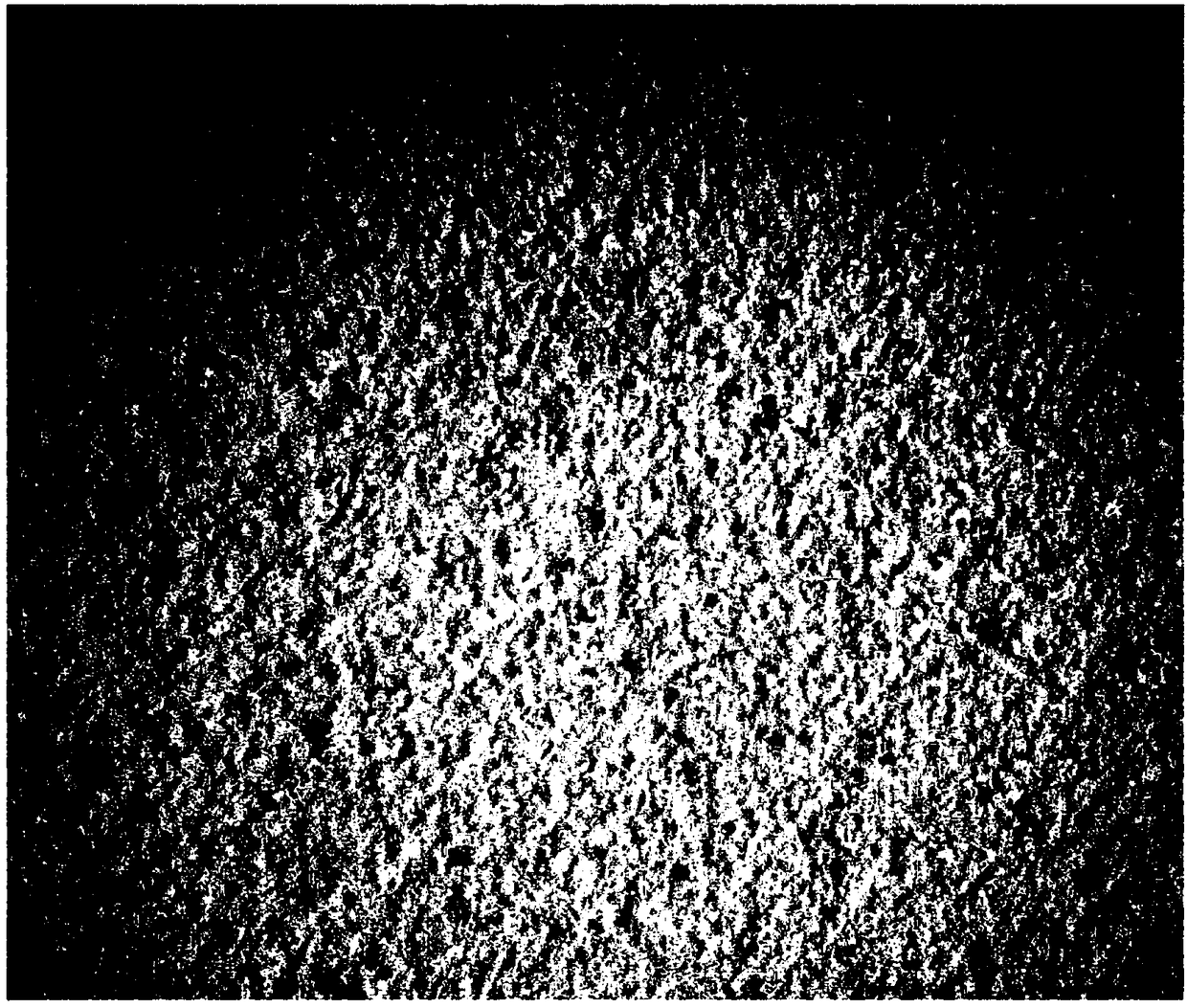
[0028] image 3 A photograph of the surface of the board is shown, and it can be seen that the coating covers the surface, somewhat hiding any directionality of the finish or surface. It can further be seen that the surface is highly irregular and matte. The surface irregularities and the presence of small pinholes in the surface coating protect the acoustic performance of the panels.

[0029] exist Figure 4 The schematic diagram of shows how the acoustic performance of a room is a...


PUM


Abstract

The present invention relates to acoustic panels, grids for acoustic panels, suspended ceiling systems and a method for producing an acoustic panel, especially a man-made vitreous fibre (MMVF) panel.The acoustic panels have a first major face and an opposite second major face, the first major face comprises a facing with a surface coating. The coating comprises microspheres to provide high lightreflection.

Description

technical field [0001] The present invention relates to an acoustic panel, a grid for an acoustic panel, a ceiling system, and a method of manufacturing an acoustic panel, in particular a man-made fiberglass (MMVF) panel, the acoustic panel having a first major surface and an opposite second major surface, wherein The first major surface includes a finish having a surface coating. Background technique [0002] Acoustic modification is an important part of creating a good indoor environment, which is gaining more and more attention in (for example) open plan offices, schools and hospitals. Noise is a distraction that can negatively impact health and productivity. A high level of acoustic comfort can be achieved using acoustic panels. [0003] In some cases, however, acoustic panels cannot be used because the surfaces of current acoustic panels are less than ideal in terms of light reflection. [0004] US2007 / 0277948 A1 discloses an acoustic brick comprising a core and a su...

Claims


Application Information

Patent Timeline
Patent Type & Authority Applications(China)
IPC IPC(8): E04B9/00E04B9/04
CPCE04B9/045E04C2/16E04B9/001
Inventor 马切伊·格热戈日·莫西亚奇
Owner ROCKWOOL AS
Learn More