Heat dissipation device of new energy vehicle

A technology for new energy vehicles and heat sinks, which is applied to the power plant, the arrangement of the cooling combination of the power plant, vehicle components, etc., can solve the problem that the temperature of the water storage tank cannot achieve the cooling effect, etc., and achieve the effect of preventing heat dissipation and reducing damage.

Inactive Publication Date: 2018-06-12
沈国友
View PDF1 Cites 2 Cited by
  • Summary
  • Abstract
  • Description
  • Claims
  • Application Information

AI Technical Summary

Problems solved by technology

[0005] The purpose of the present invention is to provide a heat sink for new energy vehicles, which has the advantage that when the fan is used to dissipate heat from the heat generating part, the heat generating part c

Method used


Image

  • Heat dissipation device of new energy vehicle
  • Heat dissipation device of new energy vehicle

Examples


Example Embodiment

[0015] The technical solutions in the embodiments of the present invention will be clearly and completely described below in conjunction with the accompanying drawings in the embodiments of the present invention. Obviously, the described embodiments are only a part of the embodiments of the present invention, rather than all the embodiments. Based on the embodiments of the present invention, all other embodiments obtained by those of ordinary skill in the art without creative work shall fall within the protection scope of the present invention.
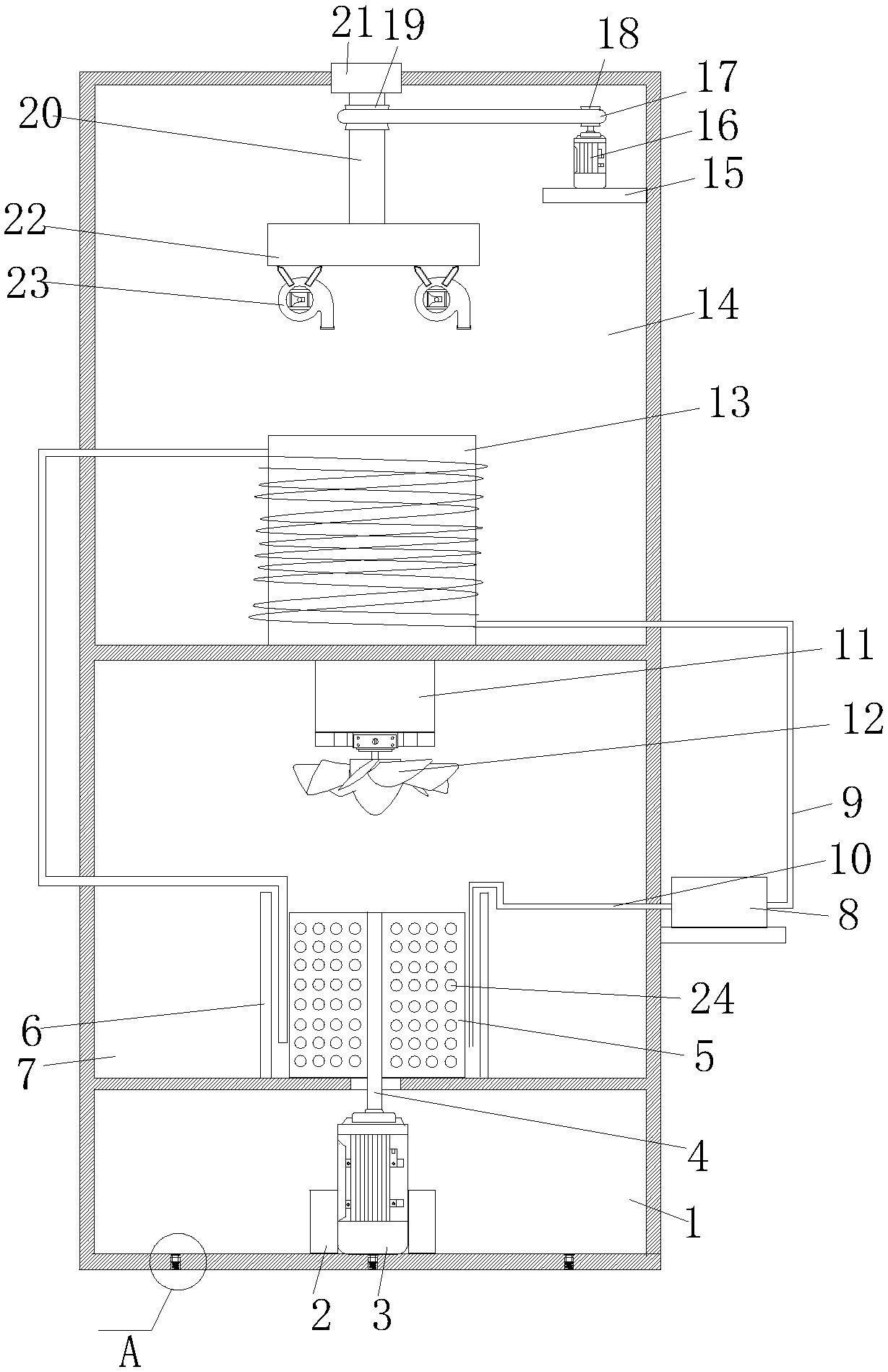
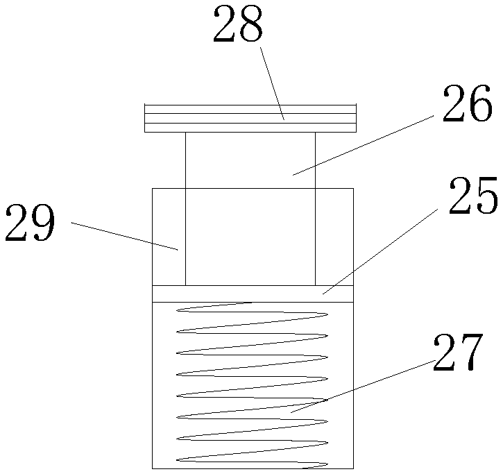
[0016] Reference Figure 1-2 , A new energy vehicle heat dissipation device, including a motor room 1, the middle of the inner bottom wall of the motor room 1 is provided with a motor fixing seat 2, the motor fixing seat 2 is provided with a No. 1 motor 3, the output end of the No. 1 motor 3 is coaxially connected with Rotating shaft 4, the upper side of the motor room 1 is provided with a No. 1 heat dissipating chamber 7, and the middle...


PUM


Abstract

The invention discloses a heat dissipation device of a new energy vehicle. The heat dissipation device of the new energy vehicle includes a motor room, wherein a motor fixed seat is arranged on the middle portion of the bottom wall of the motor room. A first motor is arranged in the motor fixed seat. The output end of the first motor is connected with a rotating shaft in a coaxial mode, and a first heat dissipation room is arranged in the upper side of the motor room. A storage water tank is arranged on the middle portion of the bottom wall of the first heat dissipation room. One end of the rotating shaft penetrates through the top wall of the motor room and the bottom wall of the storage water tank, and extends into the storage water tank. A second heat dissipation room is arranged on theupper side of the first heat dissipation room. A heating part is arranged on the middle portion of the inner bottom wall of the second heat dissipation room. A water pump is arranged on the outdoor side wall of the first heat dissipation room, and an outlet pipe is in communication with a water inlet end on the left side of the water pump. The heat dissipation device of the new energy has the advantages of enabling the heating part to achieve uniform heat dissipation. The problem that as using time goes by, the temperature of the storage water tank is getting higher and higher, and cannot achieve the cooling effect is solved.

Description

technical field [0001] The invention relates to the technical field of new energy vehicles, in particular to a radiator for new energy vehicles. Background technique [0002] New energy vehicles refer to all other energy vehicles except gasoline and diesel engines, including fuel cell vehicles, hybrid vehicles, hydrogen energy vehicles and solar vehicles. Its exhaust emissions are relatively low. According to incomplete statistics, there are more than 4 million liquefied petroleum gas vehicles and more than 1 million natural gas vehicles in the world. At present, most of the new energy vehicles on sale in the Chinese market are hybrid vehicles and pure electric vehicles. According to the definition announced by the National Development and Reform Commission of the People's Republic of China, new energy vehicles refer to the use of unconventional vehicle fuels as power sources (or the use of conventional vehicle fuels, the use of new vehicle power devices), and the power co...

Claims


Application Information

Patent Timeline
IPC IPC(8): B60K11/02
CPCY02T10/88B60K11/02
Inventor 沈国友
Owner 沈国友
Why Eureka
Try Eureka