MPCVD cavity structure and MPCVD device

A cavity and body technology, applied in metal material coating process, coating, gaseous chemical plating, etc., can solve problems such as uneven gas distribution, and achieve the effect of convenient vacuum measurement, uniform distribution, and shortened distance.

Active Publication Date: 2018-06-12
CHANGSHA ADVANCED MATERIALS IND RES INST CO LTD
View PDF9 Cites 2 Cited by
  • Summary
  • Abstract
  • Description
  • Claims
  • Application Information

AI Technical Summary

Problems solved by technology

[0004] Aiming at the deficiencies in the prior art, the present invention provides an MPCVD chamber structure to solve the problem of uneven gas distribution in the chamber of the existing MPCVD equipment, ensure the uniformity of the plasma in the chamber structure, and improve the uniformity and stability

Method used


Image

  • MPCVD cavity structure and MPCVD device
  • MPCVD cavity structure and MPCVD device
  • MPCVD cavity structure and MPCVD device

Examples


Embodiment Construction

[0038] The present invention will be described in detail below with reference to the accompanying drawings and examples. It should be noted that, in the case of no conflict, the embodiments of the present invention and the features in the embodiments can be combined with each other. For the convenience of description, if the words "up", "down", "left" and "right" appear in the following, it only means that the directions of up, down, left and right are consistent with the drawings themselves, and do not limit the structure.

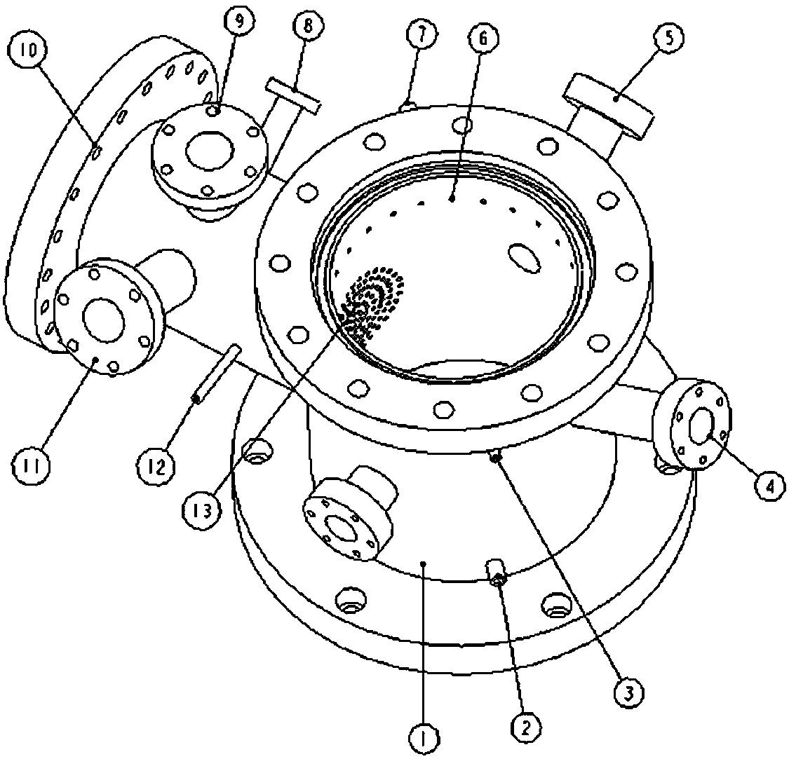
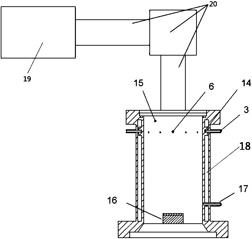
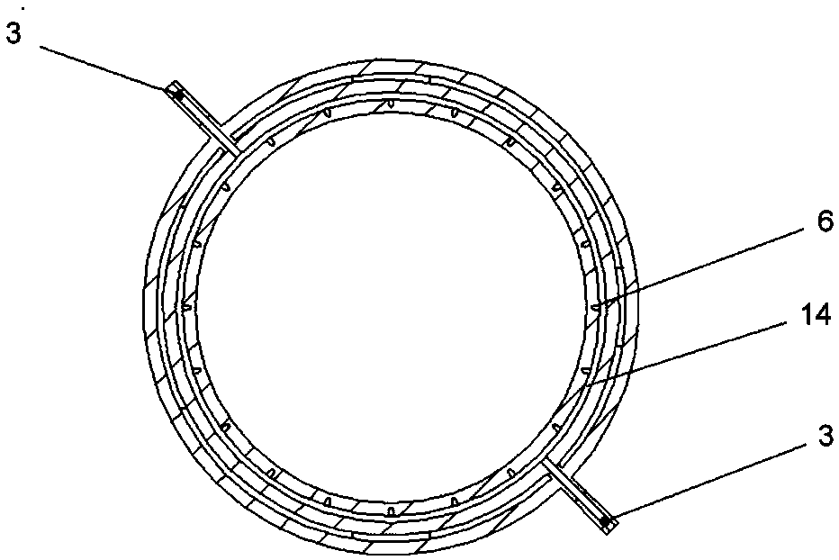
[0039] Such as figure 1 Shown is a structural schematic diagram of an MPCVD chamber structure of the present invention. The MPCVD cavity structure of the present embodiment comprises a hollow body 1, the body 1 is provided with an air inlet pipe 3, and the inner wall of the body 1 is provided with a plurality of air inlets 6 communicating with the air inlet pipe 3, each air inlet 6 Evenly distributed at the same height of the inner wall of the body 1; t...


PUM


Abstract

The invention relates to a MPCVD cavity structure and a MPCVD device. The MPCVD cavity structure and the MPCVD device comprise a hollow body. The body is provided with an air inlet pipe. The inner wall of the body is provided with a plurality of air inlets, and the air inlets are in communication with the air inlet pipe. The air inlets are at least divided into a layer. The air inlets of the samelayer evenly distributes at the same height of the inner wall of the body. The body is provided with an air outlet, and the air outlet is in communication with an inner cavity of the body. A gas in the cavity structure penetrates through the air inlet pipe and the air inlets, and uniformly enters the cavity. At the same time, the size of the air inlets is different, it is ensured that air flow ofeach air inlet is basically the same, and the uniformity of air intake is ensured. The MPCVD cavity structure and the MPCVD device are compact in design, reasonable in structure, and convenient to operate. The plasma is stable and distributes evenly, is suitable for the preparation of uniform MPCVD deposition products with large areas.

Description

technical field [0001] The invention relates to an MPCVD cavity structure and MPCVD equipment, belonging to the field of microwave plasma vapor deposition equipment. technical background [0002] Chemical vapor deposition (CVD) technology is widely used in the preparation of thin films / crystals such as diamond, diamond-like carbon, silicon oxide, and amorphous silicon. The CVD method has the advantages of low deposition temperature, easy control of film composition, and good uniformity. Among them, microwave plasma chemical vapor deposition (MPCVD) is currently the most promising method for preparing high-quality, large-area diamond because of its advantages of electrodeless discharge, less pollution, and high plasma density. The MPCVD method decomposes the gas into carbon-containing active groups through high-temperature plasma, and deposits diamonds on the substrate material under certain conditions. This method has great advantages in synthesis quality and size. [0003]...

Claims


Application Information

Patent Timeline
Patent Type & Authority Applications(China)
IPC IPC(8): C23C16/455C23C16/517
CPCC23C16/45576C23C16/517
Inventor 范杰黄翀
Owner CHANGSHA ADVANCED MATERIALS IND RES INST CO LTD
Why Eureka
Try Eureka