Thin film monitoring equipment

A technology for monitoring equipment and films, applied in transmittance measurement, mechanical thickness measurement, etc., can solve problems such as affecting production efficiency, and achieve the effect of improving production efficiency and ensuring product quality

Inactive Publication Date: 2018-06-12
余姚敏宝卫浴洁具有限公司
View PDF0 Cites 3 Cited by
  • Summary
  • Abstract
  • Description
  • Claims
  • Application Information

AI Technical Summary

Problems solved by technology

[0003] However, additional detection procedures will affect production efficiency, so how to improve production efficiency and ensure product quality is a problem to be solved urgently by those skilled in the art

Method used


Image

  • Thin film monitoring equipment
  • Thin film monitoring equipment
  • Thin film monitoring equipment

Examples


Embodiment Construction

[0013] The following description serves to disclose the present invention to enable those skilled in the art to carry out the present invention. The preferred embodiments described below are only examples, and those skilled in the art can devise other obvious variations.

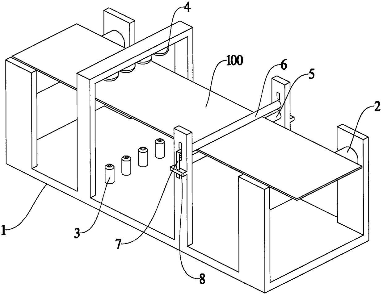
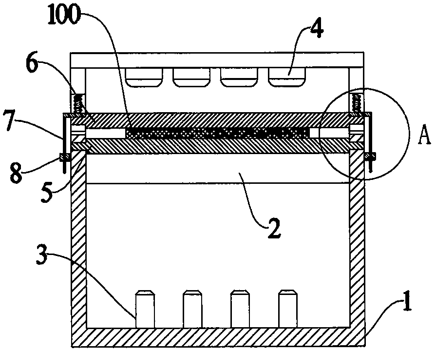
[0014] Such as Figure 1~4 As shown, the embodiment of the present invention includes a frame 1, a conveying roller 2, a transmittance measuring part and a thickness measuring part. The specific structure is as follows:

[0015] The conveying roller 2 is rotatably connected to the frame 1 for conveying the film 100 .

[0016] The light transmittance measuring component includes a laser emitter 3 and a light intensity tester 4 oppositely arranged on two sides of the film 100 . There are four laser emitters 3 and four light intensity testers 4, which are evenly distributed along the width direction of the film 100 .

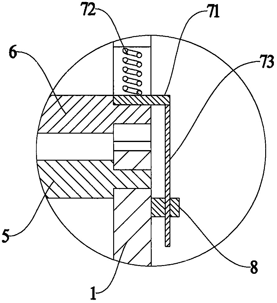
[0017] The thickness measuring components include a lower thickness measuring roller 5, a...


PUM


Abstract

The invention provides thin film monitoring equipment. The equipment is characterized by comprising a machine frame, a conveying roller, a light transmittance measuring part and a thickness measuringpart. The conveying roller is rotationally connected to the machine frame and is used for conveying a thin film. The light transmittance measuring part comprises a laser emitter and a light intensitytester which are oppositely arranged on the two sides of the thin film. The thickness measuring part comprises a lower thickness measuring roller, an upper thickness measuring roller, a displacement assembly and a displacement sensor. The lower thickness measuring roller is rotationally connected to the machine frame. The upper thickness measuring roller is located above the lower thickness measuring roller. The upper thickness measuring roller can rotate on the machine frame and can also slide up and down along the machine frame. The thin film is located between the lower thickness measuringroller and the upper thickness measuring roller and is always tightly attached to the lower thickness measuring roller and the upper thickness measuring roller. The displacement assembly is arranged between the machine frame and the upper thickness measuring roller, and can slide up and down along with the upper thickness measuring roller. The displacement sensor is arranged on the machine frame and is used for measuring the sliding distance of the displacement assembly.

Description

technical field [0001] The invention relates to the field of thin film processing, in particular to thin film monitoring equipment. Background technique [0002] The use of plastic film is more and more extensive, and its production process includes mixing, extruding, winding and other processes. After the winding is completed, it is often necessary to inspect the film, mainly to inspect the thickness and light transmittance of the film, so as to ensure the quality of the film when it leaves the factory. [0003] However, the additional detection process will affect the production efficiency, so how to improve the production efficiency and ensure the product quality is a problem to be solved urgently by those skilled in the art. Contents of the invention [0004] The main purpose of the present invention is to provide a film monitoring device, which can monitor the thickness and light transmittance of the film during the winding process, so as to improve production effici...

Claims


Application Information

Patent Timeline
Patent Type & Authority Applications(China)
IPC IPC(8): G01B5/06G01N21/59
CPCG01B5/06G01N21/59
Inventor 周栋
Owner 余姚敏宝卫浴洁具有限公司
Why Eureka
Try Eureka