Foot robot traction control method and system based on improved artificial potential field

A traction control and robot technology, applied in control/adjustment system, two-dimensional position/channel control, attitude control, etc., can solve the problem that the robot cannot reach the end point

Active Publication Date: 2018-06-12
CHINA NORTH VEHICLE RES INST
View PDF6 Cites 3 Cited by
  • Summary
  • Abstract
  • Description
  • Claims
  • Application Information

AI Technical Summary

Problems solved by technology

[0004] In order to solve the deficiencies in the above-mentioned prior art, the purpose of the present invention is to provide a footed robot traction control method and system ba

Method used


Image

  • Foot robot traction control method and system based on improved artificial potential field
  • Foot robot traction control method and system based on improved artificial potential field
  • Foot robot traction control method and system based on improved artificial potential field

Examples


Embodiment 1

[0097] The present invention provides a footed robot traction control method based on an improved artificial potential field, the flow chart of which is as follows figure 1 As shown, the method includes the following steps:

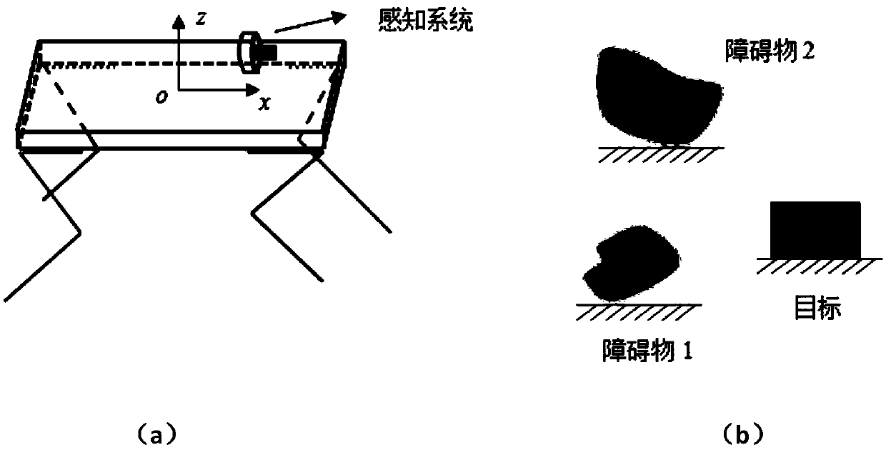
[0098] S1, extracting robot operating environment information;

[0099] S2, constructing the gravitational potential energy field of the robot target;

[0100] S3, constructing the robot obstacle repulsion potential energy field;

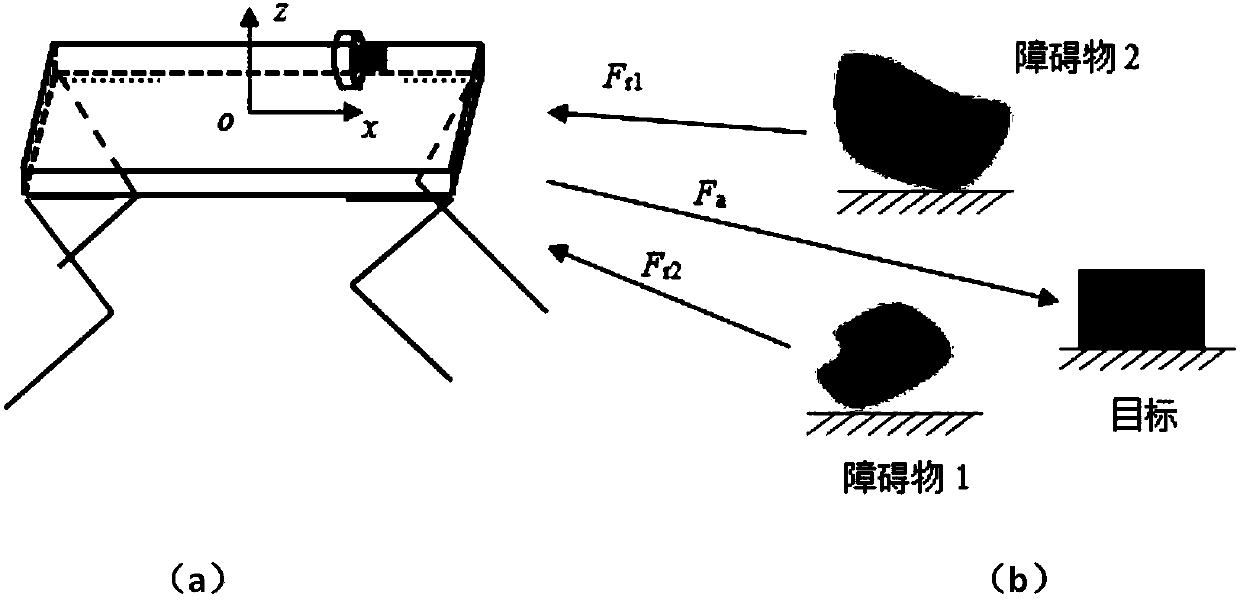
[0101] S4, establishing the virtual force of the target and the obstacle;

[0102] S5, according to the virtual resultant force generated by the environment, design the longitudinal motion control signal of the fuselage;

[0103] S6, according to the virtual gravity and repulsion generated by the environment, design the movement direction control signal of the fuselage;

[0104] S7, according to the expected body motion signal, design the body pose controller.

[0105] Such as figure 2 As shown, in S1, the robot operatin...

Embodiment 2

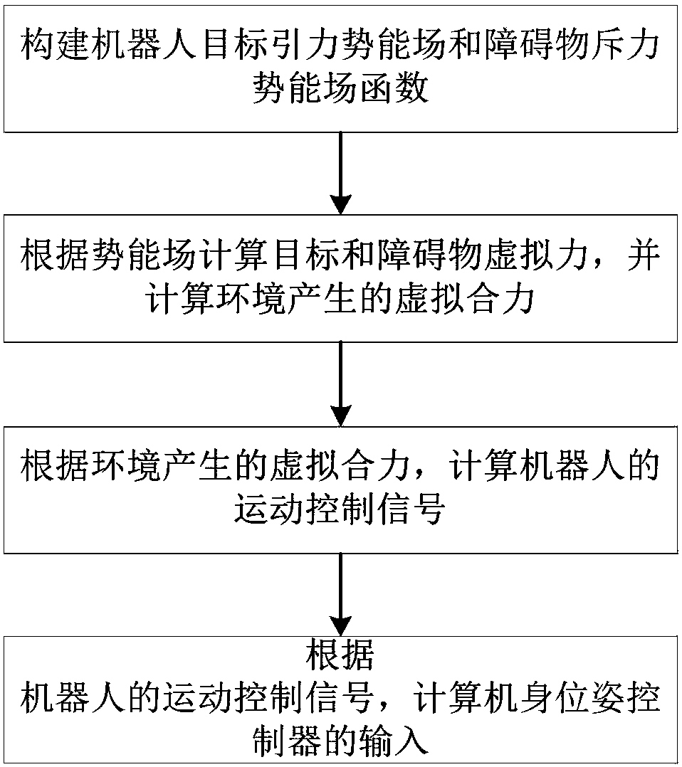
[0155] Based on the same inventive concept, the present invention also provides a footed robot traction control system based on an improved artificial potential field, its structural block diagram is as follows Figure 5 shown, including:

[0156] Construction module 201, for constructing robot target gravitational potential energy field and obstacle repulsion potential energy field function;

[0157] The first calculation module 202 is used to calculate the virtual force of the target and the obstacle according to the potential energy field, and calculate the virtual resultant force generated by the environment;

[0158] The second calculation module 203 is used to calculate the motion control signal of the robot according to the virtual resultant force generated by the environment;

[0159] The third calculation module 204 is used to calculate the input of the body pose controller based on the motion control signal of the robot.

[0160]The system also includes: an extract...


PUM


Abstract

The invention relates to a foot robot traction control method and system based on an improved artificial potential field. The method comprises steps of constructing a robot target gravitational potential energy field function and an obstacle repulsion potential energy field function; calculating a target virtual force and an obstacle virtual force according to a potential energy field, and calculating the virtual resultant force generated by the environment; based on the virtual resultant force generated by the environment, calculating the robot's motion control signal; and according to the robot's motion control signal, calculating the input of a body pose controller. The method and the system adopt an improved artificial potential field theory to overcome the defect that the robot cannotreach the end point in a local area.

Description

technical field [0001] The invention relates to the field of robot motion control, in particular to a traction control method and system for a legged robot based on an improved artificial potential field. Background technique [0002] At present, legged robots are mainly operated by remote control, which undoubtedly reduces the working efficiency of the robot. When the operator controls the robot, the human eye is used as the visual feedback. The phenomenon of repeated action adjustments of the robot has greatly caused the operator's control fatigue, and the control efficiency is low. [0003] At present, research on autonomous walking of legged robots has been carried out. The more common path planning algorithms are A* global search algorithm and genetic algorithm. Among them, the A* search algorithm is affected by the selection of heuristic functions, and it is difficult to find the global optimal solution; The structure of the algorithm is relatively complex, and the ca...

Claims


Application Information

Patent Timeline
IPC IPC(8): G05D1/02G05D1/08B62D57/032
CPCG05D1/0214G05D1/0231G05D1/0891B62D57/032
Inventor 许鹏苏波姚其昌党睿娜江磊许威蒋云峰慕林栋降晨星邓秦丹康祖铭杨超宁
Owner CHINA NORTH VEHICLE RES INST
Why Eureka
Try Eureka