
Processing method of electrode foil used for aluminum electrolytic capacitor

A technology of aluminum electrolytic capacitors and processing methods, applied in electrolytic capacitors, capacitors, circuits, etc., can solve the problems of accelerated chemical dissolution of oxide film, long boosting time, and large leakage current, so as to improve the formation efficiency and shorten the boosting time , The effect of reducing the leakage current

Inactive Publication Date: 2018-06-12
DONGGUAN DONGYANG SOLAR SCI RES & DEV CO LTD
View PDF5 Cites 3 Cited by
  • Summary
  • Abstract
  • Description
  • Claims
  • Application Information

AI Technical Summary

Problems solved by technology

[0004] However, the existing anodized foil preparation process is to apply current in each stage of formation and keep it for a period of time until the formation is completed. The resistance of the oxide film on the formed foil treated in this way is relatively high, and it is easy to generate a large amount of Joule heat when the current passes through. The chemical dissolution of the oxide film makes the quality of the oxide film not good enough, so it is not suitable to pass a large current during DC oxidation, which makes the chemical efficiency low
However, even if the current during straight-line oxidation is reduced, the obtained anode foil for aluminum electrolytic capacitors still has the problems of large leakage current and long boosting time.

Method used


Image

  • Processing method of electrode foil used for aluminum electrolytic capacitor

Examples


Embodiment 1

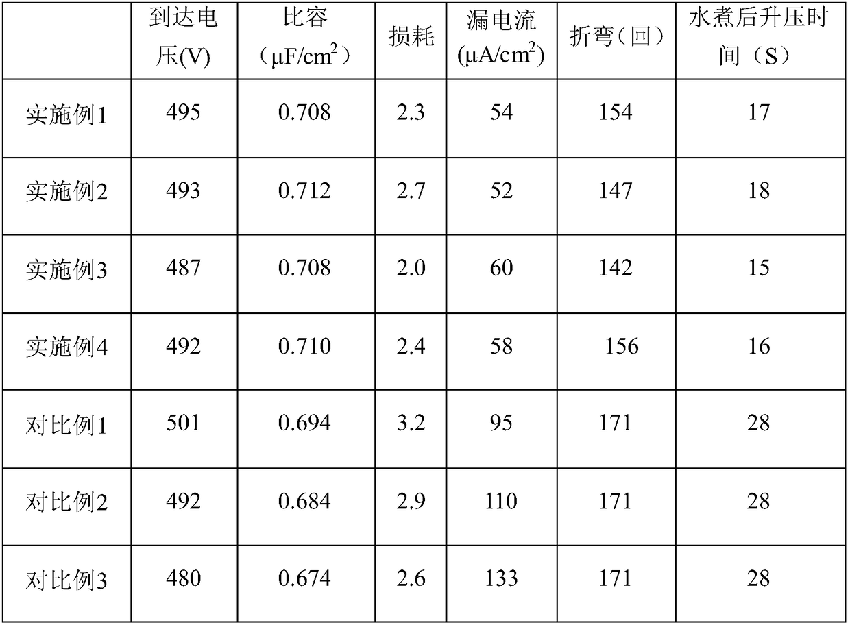
[0024] Constant current boost (10A / cm 2 ) → positive constant voltage (150V, 10S) → stop (1S) → negative constant voltage (150V, 2S) → stop (1S) → ... cycle 10 times → positive constant voltage (300V, 10S) → stop ( 1S)→Negative constant voltage (300V, 2S)→Stop (1S)→…cycle 10 times→Positive constant voltage (450V, 10S)→Stop (1S)→Negative constant voltage (450V, 2S)→Stop (1S)→...cycle 10 times→positive constant voltage (500V, 10S)→stop (1S)→negative constant voltage (500V,2S)→stop (1S)→...cycle 10 times→burning (2min )→500V supplementary formation (positive constant voltage 10S, stop 1S, negative constant voltage 2S, cycle 10 times). The test results are shown in Table 1.

Embodiment 2

[0026] Constant current boost (80A / cm 2 )→Positive constant voltage (150V, 20S)→Stop (1S)→Negative constant voltage (150V, 2S)→Stop (1S)→...cycle 15 times→Positive constant voltage (300V, 20S)→Stop ( 1S)→Negative Constant Voltage (300V, 2S)→Stop (1S)→...Cycle 15 times→Positive Constant Voltage (450V, 20S)→Stop (1S)→Negative Constant Voltage (450V, 2S)→Stop (1S)→...cycle 15 times→positive constant voltage (500V, 20S)→stop (1S)→negative constant voltage (500V,2S)→stop (1S)→...cycle 15 times→burning (2min )→500V supplementary formation (positive constant voltage 20S, stop 1S, negative constant voltage 2S cycle 15 times). The test results are shown in Table 1.

Embodiment 3

[0028] Constant current boost (60A / cm 2 ) → positive constant voltage (150V, 20S) → stop (1S) → negative constant voltage (150V, 1S) → stop (1S) → ... cycle 10 times → positive constant voltage (300V, 20S) → stop ( 1S)→negative constant voltage (300V, 1S)→stop (1S)→…cycle 10 times→positive constant voltage (450V,20S)→stop (1S)→negative constant voltage (450V,1S)→stop (1S)→...cycle 10 times→positive constant voltage (500V, 20S)→stop (1S)→negative constant voltage (500V,1S)→stop (1S)→...cycle 10 times→burning (2min )→500V supplementary formation (positive constant voltage 20S, stop 1S, negative constant voltage 1S cycle 10 times). The test results are shown in Table 1.


PUM


Abstract

The invention discloses a processing method of an electrode foil used for an aluminum electrolytic capacitor. The method comprises pre-processing, corrosion, postprocessing and multistage formation. The method is characterized in that in each stage of formation, an asymmetrical intermittent positive and negative combination pulse power up mode is used to carry out formation. Compared with an existing continuous power up formation mode, by using the method of the invention, the quality of a formed foil can be greatly improved, boost time is shortened, a leakage current is reduced and formationefficiency is increased.

Description

technical field [0001] The invention relates to a processing method for an electrode foil used in an aluminum electrolytic capacitor, and belongs to the technical field of new energy aluminum capacitors. technical background [0002] As an indispensable electronic component in the production of electronics industry, aluminum electrolytic capacitor has the characteristics of large demand and wide range of use, and has always occupied a considerable proportion in the entire capacitor industry market. With the rapid development of science and technology and the continuous improvement of market demand, aluminum electrolytic capacitors are more and more widely used in the fields of air conditioner inverters, spot welding machines, charging piles and UPS equipment, so the requirements for product performance are also getting higher and higher. . [0003] At present, the preparation process of aluminum foil for solid aluminum electrolytic capacitors generally includes: light foil ...

Claims


Application Information

Patent Timeline
Patent Type & Authority Applications(China)
IPC IPC(8): H01G9/045H01G9/055
CPCH01G9/045H01G9/055
Inventor 余英凤邓利松何凤荣
Owner DONGGUAN DONGYANG SOLAR SCI RES & DEV CO LTD
Learn More