Agglomeration device for heterogeneous condensation and turbulent agglomeration coupling and application thereof

A vapor phase, turbulent flow technology, applied in electrostatic effect separation, auxiliary pretreatment, solid separation and other directions, can solve problems such as unfavorable normal operation of equipment, affecting the development of front vortices, affecting the agglomeration effect, etc., achieving easy processing and promotion, simple installation, Increase the effect of fluid turbulence

Active Publication Date: 2018-06-15
HEBEI UNIV OF TECH
View PDF10 Cites 2 Cited by
  • Summary
  • Abstract
  • Description
  • Claims
  • Application Information

AI Technical Summary

Problems solved by technology

[0004] Liu Hanxiao (Liu Hanxiao. Eddy aggregation and numerical simulation of coal-fired ultrafine particles [D]. North China Electric Power University, 2012.) designed an agglomeration device. Four triangular prisms were arranged near the entrance to divert the flow. Then three rows of Z-shaped vortex sheets are arranged at the rear, with six vortex sheets in each row. The angle of the Z-shaped vortex sheets is perpendicular to the direction of the incoming smoke. The blades affect the development of the front vortex, destroy the formed vortex, and then affect the reunion effect; in addition, due to the excessive number of vortex sheets, the resistance will increase and the pressure drop will increase, which is not conducive to the normal operation of the equipment.

Method used


Image

  • Agglomeration device for heterogeneous condensation and turbulent agglomeration coupling and application thereof
  • Agglomeration device for heterogeneous condensation and turbulent agglomeration coupling and application thereof
  • Agglomeration device for heterogeneous condensation and turbulent agglomeration coupling and application thereof

Examples


Embodiment 1

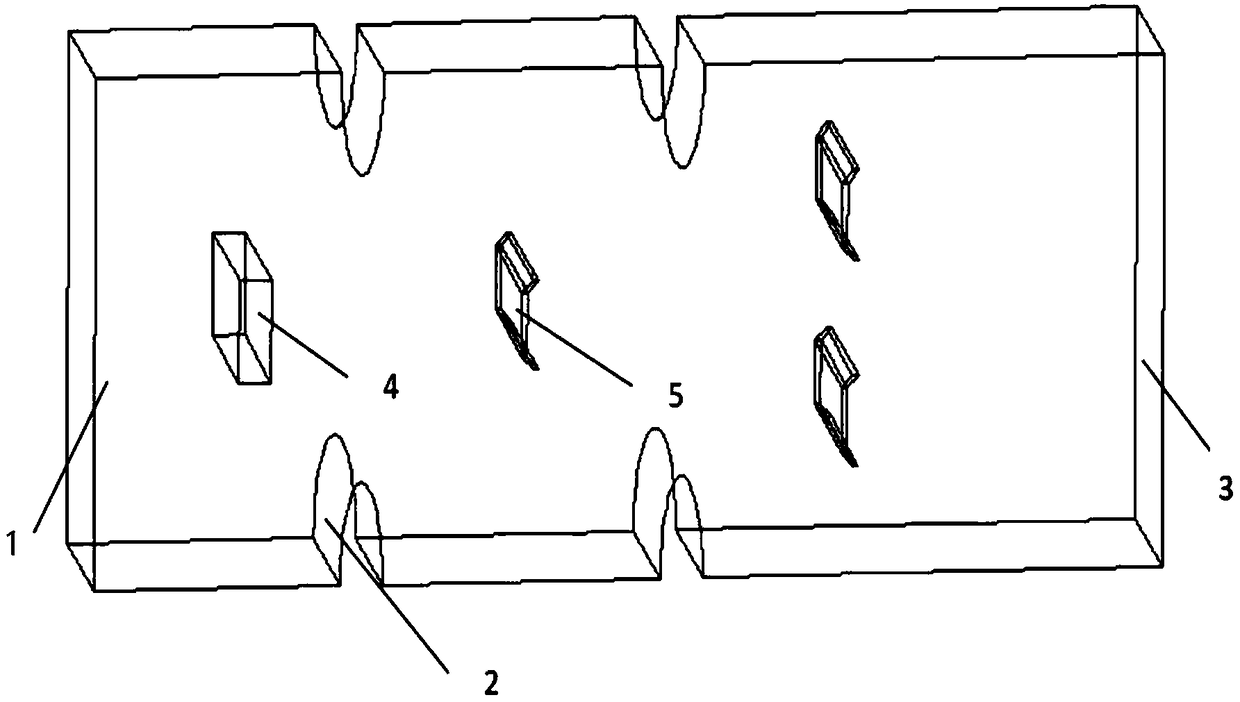
[0039] The agglomeration device in this embodiment is generally in the shape of a cuboid, but its boundary is provided with a semi-elliptical cylindrical protrusion, and the overall structure is axially symmetrical with respect to the direction of the incoming smoke. The left end of the reunion device is the flue gas inlet 1, which is connected to the desulfurization equipment, and the right end is the flue gas outlet 3, which is connected to the wet electrostatic precipitator. The interior of the agglomeration device includes a cuboid spoiler column 4 with the function of injecting steam and a C-shaped spoiler vortex 5. The center line of the cuboid spoiler column 4 with the function of injecting steam is located on the center line of the agglomeration device, and the cuboid spoiler column is close to the flue gas. The entrance position, its top view is a rectangle, the long side is perpendicular to the direction of flue gas flow, the first row of C-shaped spoiler vortex 5 is ...


PUM


Abstract

The invention relates to an agglomeration device for heterogeneous condensation and turbulent agglomeration coupling and application thereof. The agglomeration device is generally in a rectangular parallelepiped shape and generally of an axially symmetric structure in the direction of incoming flue gas, the left end of an agglomeration device body is a flue gas inlet and is connected with a desulfurization device, and the right end of the agglomeration device body is a flue gas outlet and is connected with a wet electrostatic precipitator; a plurality of semi-elliptical cylindrical protrusionsare symmetrically arranged on the upper and lower side walls of the rectangular parallelepiped along a central axis of the device body, the upper and lower opposite semi-elliptical cylindrical protrusions serve as a group, there are altogether n groups, and n is greater than or equal to 2; the lowest point of each semi-elliptical cylindrical protrusion faces toward the interior of the device body; a rectangular parallelepiped pin fin is arranged between the first group of semi-elliptical cylindrical protrusions and the flue gas inlet, the center line of the rectangular parallelepiped pin fincoincides with the central axis of the device body, the rectangular parallelepiped pin fin is of a hollow cavity structure, and the upper and lower surfaces of the rectangular parallelepiped pin fin are both provided with a steam nozzle. According to the device, the particle size of ultrafine particles is increased by means of a heterogeneous condensation and turbulent agglomeration coupling mode,and the structure is simple.

Description

technical field [0001] The invention relates to the technical field of processing ultrafine particles in coal-fired flue gas, and specifically belongs to an agglomeration device coupled with steam phase change and turbulent flow agglomeration and its application. Background technique [0002] PM2.5, also known as particulate matter that can enter the lungs, refers to fine particles with an aerodynamic equivalent diameter less than or equal to 2.5 μm. PM2.5 not only causes smoggy weather and affects people's daily activities, but also has serious harm to human breathing and cardiovascular system. Coal-fired boilers are an important part of modern production and are also the main source of PM2.5 emissions. At present, electrostatic precipitators and bag filters are mainly used to remove particles in flue gas. Electrostatic precipitators and bag filters are better for removing particles with larger particle sizes in flue gas, but for ultrafine particles due to Its high specif...

Claims


Application Information

Patent Timeline
Patent Type & Authority Applications(China)
IPC IPC(8): B01D51/02B03C3/01
CPCB01D51/02B03C3/01
Inventor 陈占秀朱洪漫杨历苗瑞灿闵春华刘联胜
Owner HEBEI UNIV OF TECH
Why Eureka
Try Eureka