A Manufacturing Method of Blind Wave Roof with Reduced Processing Cost

A technology of manufacturing method and processing cost, which is applied in the field of container roof manufacturing, can solve the problems of high procurement cost, and achieve the effects of good synchronization, improved processing efficiency, and smooth movement

Active Publication Date: 2019-07-30
安徽金大进重工机床有限公司
View PDF14 Cites 0 Cited by
  • Summary
  • Abstract
  • Description
  • Claims
  • Application Information

AI Technical Summary

Problems solved by technology

[0007] The purpose of the present invention is to overcome the problem of high procurement cost of existing blind wave roof forming equipment, and provide a blind wave roof manufacturing method that reduces processing costs. The overall price of this model is only tens of thousands of yuan. Compared with the traditional bending machine and a complete set of mold pressing process, it greatly reduces the cost of equipment procurement and reduces the economic burden of small and medium-sized container roof manufacturers.

Method used


Image

  • A Manufacturing Method of Blind Wave Roof with Reduced Processing Cost
  • A Manufacturing Method of Blind Wave Roof with Reduced Processing Cost
  • A Manufacturing Method of Blind Wave Roof with Reduced Processing Cost

Examples


Embodiment 1

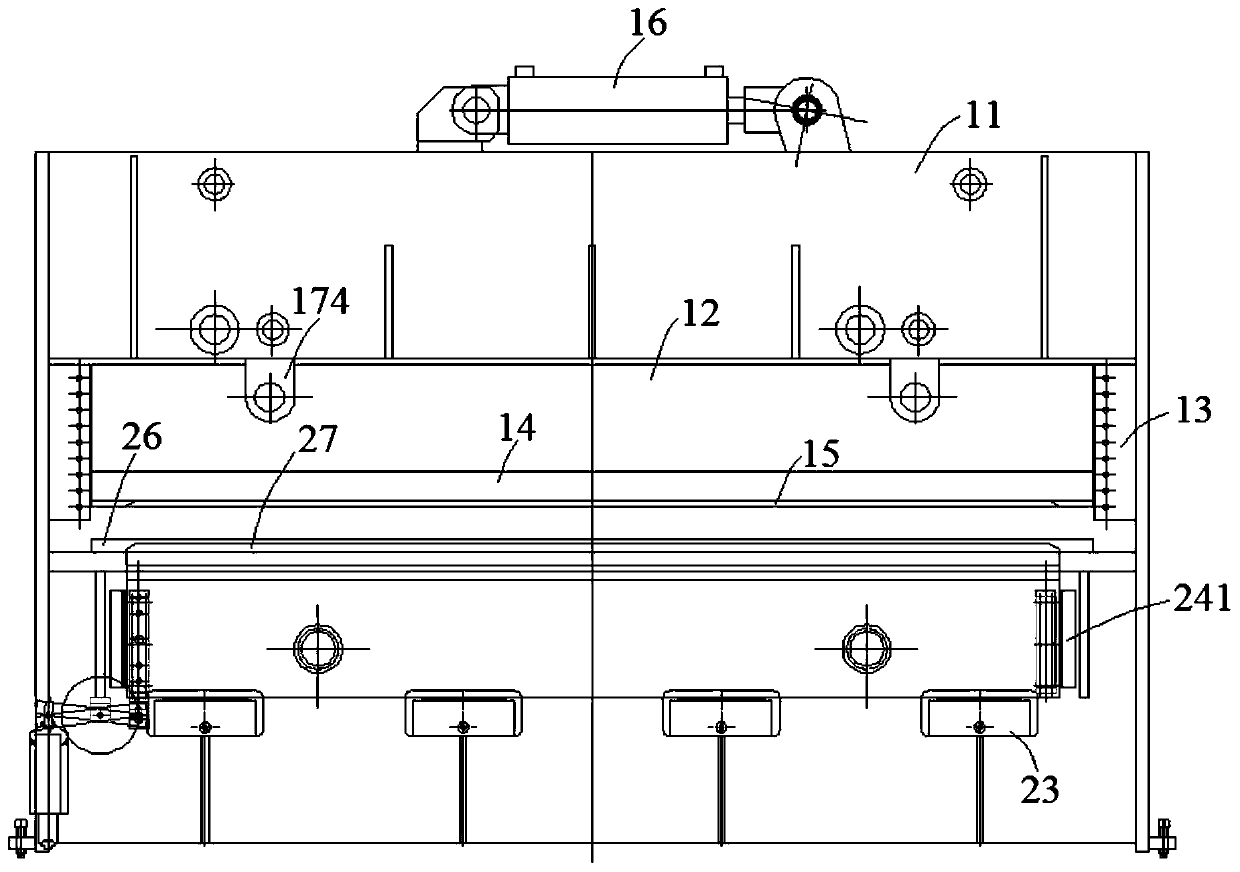
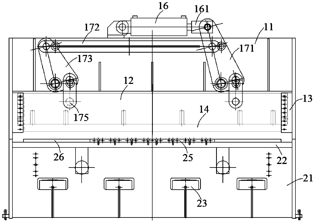
[0051] combine figure 1 with image 3 , a kind of special-purpose hydraulic press for blind-wave roof manufacturing that reduces processing costs in this embodiment includes an upper box body 11, an upper slider 12, an upper mold 15, an upper main oil cylinder 16, a lower box body 21, a lower main oil cylinder 23, a sliding Block 24 and lower mold 27. Described upper master oil cylinder 16 is arranged on upper box body 11 tops, and upper slide block 12 is arranged on upper box body 11 bottoms, and upper mold base 14 is arranged at the bottom of upper slide block 12, and upper mold base 15 is fixed on upper mold base 14.

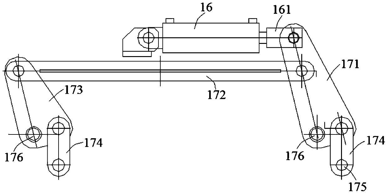
[0052] A drive unit is arranged between the upper master oil cylinder 16 and the upper slider 12, combined with figure 2 , the drive unit includes a main swing link 171, a beam 172, a secondary swing link 173 and a vertical link 174, one end of the beam 172 is connected to the main swing link 171, and the other end is connected to the secondary swing link...

Embodiment 2

[0057] combine Figure 5 , Image 6 , Figure 7 with Figure 8 , a kind of special-purpose hydraulic press for blind-wave top plate manufacturing of this embodiment that reduces processing costs is basically the same as Embodiment 1, and its difference is that: this embodiment further optimizes the design of the upper die 15, the lower die 27 and the blank holder 26, Specifically: the upper die 15 is set as a die, and threaded holes are set around the die cavity, and the die is inserted into the threaded holes by bolts to be connected with the upper die holder 14 at the bottom of the upper slide block 12 . The lower die 27 is a convex die, and threaded holes are arranged along the length direction of the lower die 27, and the lower die 27 is inserted into the threaded holes by bolts to be connected with the lower block 24. The upper die 15, the blank holder 26 and the lower die 27 are all designed with a large arc surface along the length direction.

[0058] It is worth no...

Embodiment 3

[0060] combine Figure 9 , a kind of special-purpose hydraulic press for blind-wave top plate manufacturing of this embodiment that reduces processing costs is basically the same as Embodiment 2, and its difference is that: this embodiment is also provided with a back gauge device on one side of the moving direction of the lower box 21 plates , the backgauge device pulls the plate to move horizontally in one direction. The back gauge device includes a motor 31, a rear support plate 32, a screw rod 33, a sliding seat 341, a finger 346, a front support plate 36 and a sprocket 37, and the front support plate 36 is connected to the lower box 21 through a screw 361 , said screw rod 33 is provided with two, and two screw rods 33 are straddled in parallel between the front support plate 36 and the rear support plate 32, and one end of one of the screw rods 33 is connected with the motor 31, and the other end is provided with a chain Wheel 37; Another screw mandrel 33 one ends also a...


PUM


Abstract

The invention discloses a blind wave top plate manufacturing method capable of reducing machining cost, and belongs to the technical field of blind wave top plate manufacturing. The blind wave top plate manufacturing method comprises the manufacturing steps that 1, a continuous coil steel is uncoiled, and is discharged to be a steel plate of a certain length; 2, the to-be-moulded steel plate is placed on an edge pressing ring on a worktable; 3, a piston of an upper main oil cylinder moves horizontally, and two vertical connection rods drive an upper mould to move downwards to closely press theto-be-moulded steel plate; 4, a lower mould is driven to move vertically by a lower main oil cylinder, and a blind wave is formed on the to-be-moulded steel plate in one step; 5, motors drive lead screws to rotate; slide bases sleeving the two lead screws move horizontally, and a baffle finger drives the steel plate to move to be subjected to moulding operation of a next blind wave; and 6, the moulded steel plate is subjected to positioning and trimming treatment sequentially. According to the manufacturing technique provided by the invention, the special machine designed for the blind wave top plate structure is used; equipment purchasing cost is greatly reduced; and financial load of middle and small container top plate manufacturing enterprises is alleviated.

Description

technical field [0001] The invention relates to the technical field of container roof manufacturing, and more specifically, relates to a method for manufacturing a blind wave roof that reduces processing costs. Background technique [0002] As a general means of transportation, containers have played a great role in the existing logistics industry. At present, the commonly used container roof generally adopts the blind wave roof, and the specific structure can be found in Figure 10 A plurality of blind waves 41 are arranged on the container roof 4, and the structure of the blind waves 41 protrudes upward from the container roof 4 and is closed around. The blind wave 41 of the container roof 4 is integrally formed. [0003] The hydraulic press is an important forming equipment. The motor drives the hydraulic pump to generate high-pressure liquid, and the hydraulic cylinder generates linear motion to work. Due to the wide adaptability of hydraulic machining, it is widely us...

Claims


Application Information

Patent Timeline
Patent Type & Authority Patents(China)
IPC IPC(8): B21D22/22B21D37/10B21D24/00B21D24/14
CPCB21D22/22B21D24/00B21D24/14B21D37/10
Inventor 王大进王启岗
Owner 安徽金大进重工机床有限公司
Why Eureka
Try Eureka