
An automatic sandblasting machine

A sandblasting machine, automatic technology, applied in the mechanical field, can solve the problems of uneven sandblasting consistency, affecting the appearance and subsequent processing, and inconvenient use of the sandblasting machine, so as to improve work efficiency and quality, and save internal space , the effect of improving consistency

Active Publication Date: 2019-12-17
南通迅通金属制品有限公司
View PDF9 Cites 0 Cited by
  • Summary
  • Abstract
  • Description
  • Claims
  • Application Information

AI Technical Summary

Problems solved by technology

[0002] Due to the impact and cutting effect of abrasives on the surface of the workpiece, the surface of the workpiece can be obtained with a certain degree of cleanliness and different roughness, so that the mechanical properties of the surface of the workpiece are improved, thus improving the fatigue resistance of the workpiece and increasing its The adhesion between the coating and the coating prolongs the durability of the coating film, and is also conducive to the leveling and decoration of the coating. It removes impurities, variegated colors and oxide layers on the surface, and at the same time roughens the surface of the medium to eliminate the residual stress of the workpiece. And improve the surface hardness of the substrate, the traditional sandblasting machine is very inconvenient to use, requiring operators to participate in the operation, so that the efficiency of the blasting is not high, the consistency of the sandblasting is uneven, affecting the appearance and subsequent processing, ultimately affect the quality of the product

Method used


Image

  • An automatic sandblasting machine
  • An automatic sandblasting machine
  • An automatic sandblasting machine

Examples


Embodiment Construction

[0028] The following will clearly and completely describe the technical solutions in the embodiments of the present invention with reference to the accompanying drawings in the embodiments of the present invention. Obviously, the described embodiments are only some of the embodiments of the present invention, not all of them. All other embodiments obtained by persons of ordinary skill in the art based on the embodiments of the present invention belong to the protection scope of the present invention.

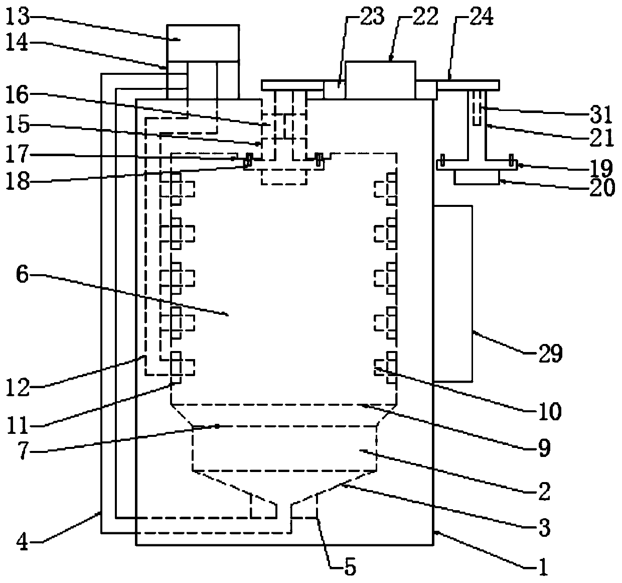
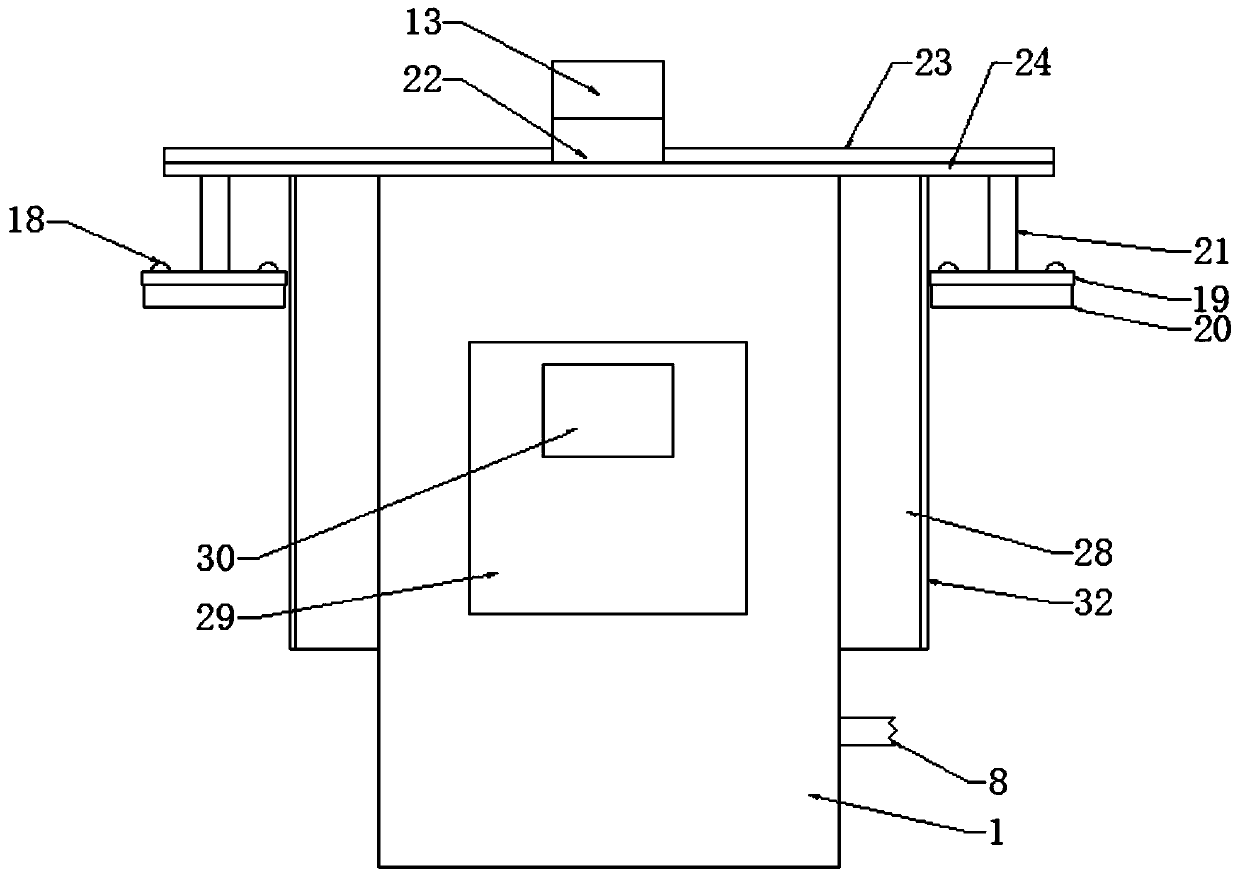
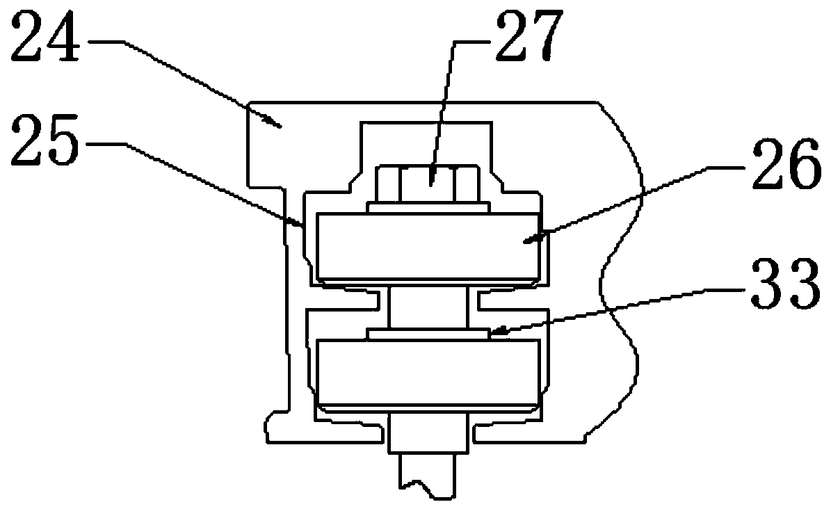
[0029] According to an embodiment of the present invention, an automatic sandblasting machine is provided.

[0030] Such as Figure 1-3 As shown, an automatic sandblasting machine according to an embodiment of the present invention includes a machine cover 1, the machine cover 1 is a cavity structure, and the inner lower part of the machine cover 1 is provided with an abrasive box 2, and the abrasive box 2 The bottom of the funnel 3 is provided with a funnel 3, the bottom of th...


PUM


Abstract

The invention discloses an automatic sandblasting machine. The automatic sandblasting machine includes a machine mask, wherein the machine mask is of a cavity structure. The lower portion of the innerside of the machine mask is provided with an abrasive box, a funnel is arranged at the bottom portion of the abrasive box, and a feeding pipe is arranged at the bottom portion of the funnel. One end,near to the funnel, of the feeding pipe is provided with a first adjustment valve, a grinding cavity is formed in the top portion of the abrasive box, and a filter net is arranged between the abrasive box and the grinding cavity. One side of the machine mask is provided with a waste draining pipe, the waste draining pipe corresponds to the filter net, and a protective net is arranged at the lowerportion of the inner side of the grinding cavity. The inner side wall of the grinding cavity is provided with a plurality of material praying guns. The material praying guns are evenly provided withsecond adjustment valves, and one ends, near to the inner wall of the grinding cavity of the material praying guns penetrate through the grinding cavity and are fixedly connected with air inlet pipes.The automatic sandblasting machine has the beneficial effects that the efficiency of spraying and grinding is improved, the consistency is improved, the appearance and subsequent processing are ensured, and the quality of the final product is guaranteed.

Description

technical field [0001] The invention relates to the field of machinery, in particular to an automatic sandblasting machine. Background technique [0002] Due to the impact and cutting effect of abrasives on the surface of the workpiece, the surface of the workpiece can be obtained with a certain degree of cleanliness and different roughness, so that the mechanical properties of the surface of the workpiece are improved, thus improving the fatigue resistance of the workpiece and increasing its The adhesion between the coating and the coating prolongs the durability of the coating film, and is also conducive to the leveling and decoration of the coating. It removes impurities, variegated colors and oxide layers on the surface, and at the same time roughens the surface of the medium to eliminate the residual stress of the workpiece. And improve the surface hardness of the substrate, the traditional sandblasting machine is very inconvenient to use, requiring operators to partici...

Claims


Application Information

Patent Timeline
Patent Type & Authority Patents(China)
IPC IPC(8): B24C3/02B24C7/00B24C9/00
CPCB24C3/02B24C7/0046B24C9/00B24C9/006
Inventor 王华亮赵清昕
Owner 南通迅通金属制品有限公司
Learn More