
Pollutant removing device for sewage pipe

A technology for sewage pipelines and cleaning, which is applied in water supply installations, waterway systems, buildings, etc., and can solve problems such as low operation efficiency, poor working environment, and high labor intensity.

Pending Publication Date: 2018-06-15
苏州思上环保科技有限公司
View PDF0 Cites 1 Cited by
  • Summary
  • Abstract
  • Description
  • Claims
  • Application Information

AI Technical Summary

Problems solved by technology

Sewage treatment needs to pass through a series of treatment equipment, and the pipeline is used to connect various sewage treatment equipment. After a long period of use, the inner wall of the pipeline will often adhere to a large amount of dirt, so the pipeline needs to be cleaned. Manual work is not only labor-intensive, but also the working environment is poor and the work efficiency is low

Method used


Image

  • Pollutant removing device for sewage pipe
  • Pollutant removing device for sewage pipe
  • Pollutant removing device for sewage pipe

Examples


Embodiment Construction

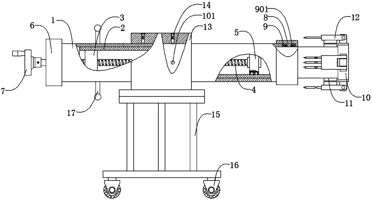
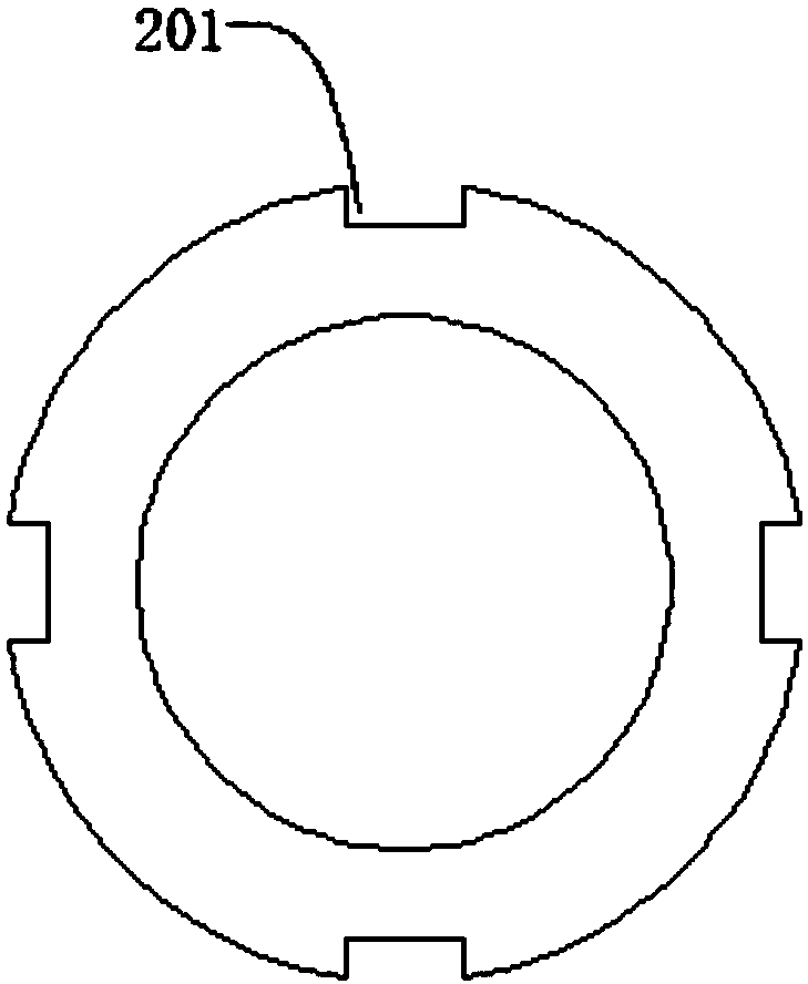
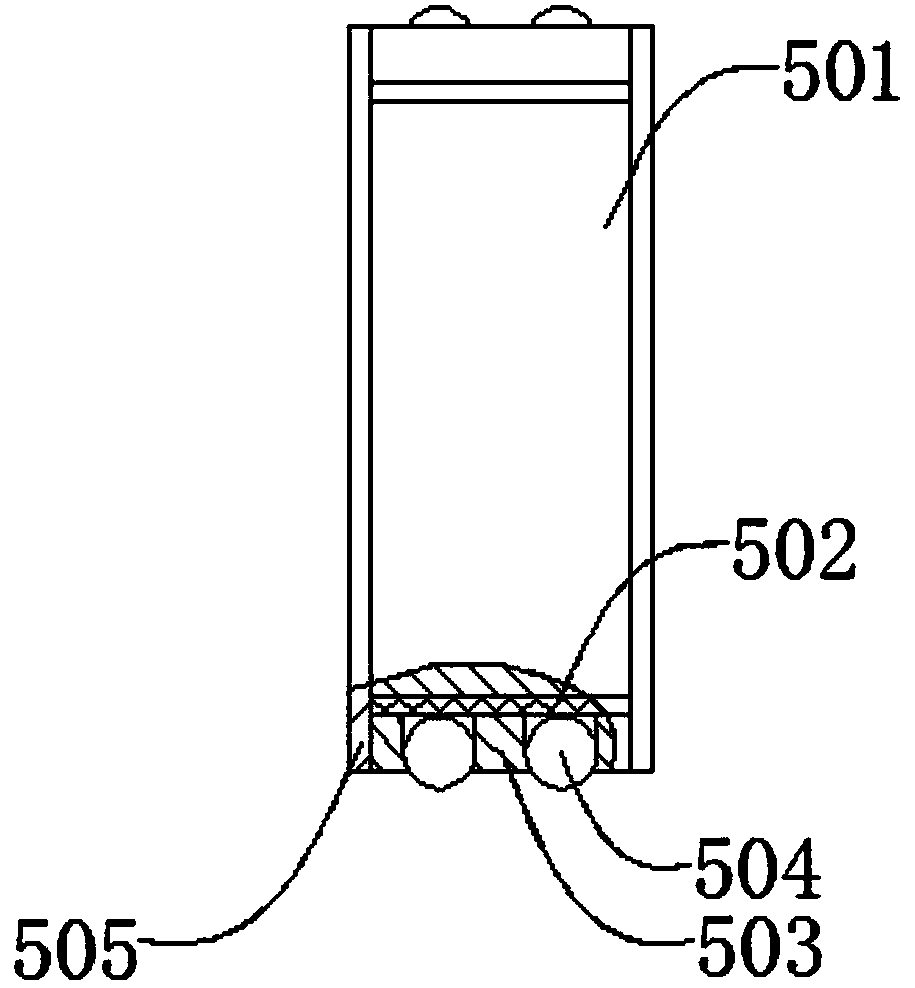
[0023] like figure 1 , figure 2 , image 3 , Figure 4 , Figure 5 , Image 6As shown, a sewage pipeline cleaning device includes an outer sleeve 1, an inner sleeve 2, a feed nut 3, a screw 4, a floating support mechanism 5, an end cover 6, a hand wheel 7, a guide sleeve 8, and a sealing seat 9 , a transition plate 10, an inner magnet 11, a slag hanging mechanism 12, a support swivel seat 13, a locking mechanism 14, a bracket 15, a universal wheel 16, and a handle 17, the inner casing 2 is located inside the outer casing 1, and the The inner sleeve 2 can slide left and right along the outer sleeve 1, the feed nut 3 is located at the inner left end of the inner sleeve 2, the feed nut 3 is welded to the inner sleeve 2, and the screw 4 runs through Feed nut 3, the lead screw 4 is threadedly connected with the feed nut 3, the floating support mechanism 5 is located at the inner right end of the inner casing 2 and penetrated by the lead screw 4, the floating support mechanism...


PUM


Abstract

The invention discloses a pollutant removing device for a sewage pipe. The pollutant removing device for the sewage pipe comprises an outer sleeve, an inner sleeve, a feeding nut, a lead screw, a floating supporting mechanism, an end cover, a hand wheel, a guiding sleeve, a sealing base, a transition disc, an inner magnet, dreg hanging mechanisms, a supporting rotating base, locking mechanisms, supports, universal wheels and a handle, wherein the hand wheel is rotated to drive the lead screw to rotate, the inner sleeve fixedly connected with the feeding nut slides out along the outer sleeve, and then the device is pushed to extend into a pipe with pollutants needing to be removed; as the dreg hanging mechanisms are in the open states, rake nails are in contact with the inner wall of the pipe, the dreg hanging mechanisms are pulled back by shaking the hand wheel, pollutants on the inner side of the pipe are removed through the rake nails, the outer sleeve is rotated by the handle, angles of the dreg hanging mechanisms are adjusted accordingly, and dead-angle-free cleaning of the pipe is achieved. The pollutant removing device is simple in structure, the pollutants on the inner sideof the pipe can be automatically removed, dead-angle-free pollutant removing is achieved, the pollutant removing effect is effectively improved, the labor intensity of operators is reduced, and the comfortable degree and the efficiency of pollutant removing are improved.

Description

technical field [0001] The invention relates to a mechanical device, in particular to a sewage pipeline cleaning device. Background technique [0002] The process of purifying sewage to meet the water quality requirements for discharge into a certain water body or reuse is called sewage treatment. Sewage treatment is widely used in various fields such as construction, agriculture, transportation, energy, petrochemical, environmental protection, urban landscape, medical treatment, catering, etc., and it is also increasingly entering the daily life of ordinary people. Sewage treatment needs to pass through a series of treatment equipment, and the pipeline is used to connect various sewage treatment equipment. After a long period of use, the inner wall of the pipeline will often adhere to a large amount of dirt, so the pipeline needs to be cleaned. Manual operation is not only labor-intensive, but also the working environment is poor and the operation efficiency is low. In vi...

Claims


Application Information

Patent Timeline
IPC IPC(8): E03F7/10
CPCE03F7/10
Inventor 钱淑娇罗剑
Owner 苏州思上环保科技有限公司
Learn More