Screw drill tool by-pass valve with large displacement flow dividing function and using method thereof

A technology of screw drilling tools and shunt action, which is applied in the valve device of wellbore/well, earth-moving drilling, special data processing applications, etc. It has the problems of low output speed and torque, complex structure, etc.

Active Publication Date: 2018-06-15
CHINA UNIV OF PETROLEUM (EAST CHINA) +2
View PDF8 Cites 3 Cited by
  • Summary
  • Abstract
  • Description
  • Claims
  • Application Information

AI Technical Summary

Problems solved by technology

[0003] Screw drilling tools have strict requirements on drilling fluid displacement. If the drilling fluid displacement is low, the output speed and torque of the screw drilling tool will be low, which is difficult to meet the drilling requirements; if the displacement is high, the output speed and torque will be high, which is easy Lead to premature damage of the screw drilling tool, and it is difficult to meet the drilling requirements
When drilling large-size well sections, highly deviated well sections and horizontal sections, it is often required to use a large drilling fluid displacement to improve rock-carrying efficiency. The rated displacement of ordinary screw drilling tools is difficult to meet the large displacement requirements. In this case It is necessary to adopt hollow rotor screw drilling tools with complex structure and high cost

Method used


Image

  • Screw drill tool by-pass valve with large displacement flow dividing function and using method thereof
  • Screw drill tool by-pass valve with large displacement flow dividing function and using method thereof
  • Screw drill tool by-pass valve with large displacement flow dividing function and using method thereof

Examples


Embodiment Construction

[0072] Aiming at the technical problems that ordinary screw drilling tools are difficult to use for large-displacement circulation drilling, the structure of the hollow rotor screw drilling tool is complex, and the cost is high, the invention provides a design and application of a new screw drilling tool bypass valve with flow diversion function method, large displacement circulation and drilling can be used to replace the existing hollow rotor design, which helps to improve the rock-carrying efficiency of large-scale well sections, highly deviated well sections and horizontal sections, reduce drilling risks and increase drilling speed .

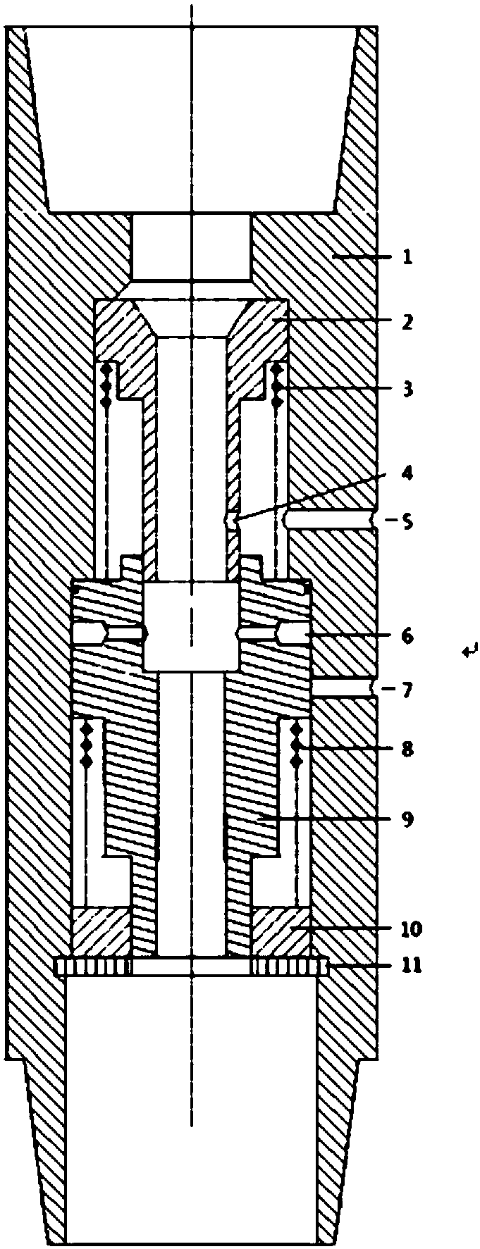
[0073] The present invention will be described in detail below in conjunction with the accompanying drawings.

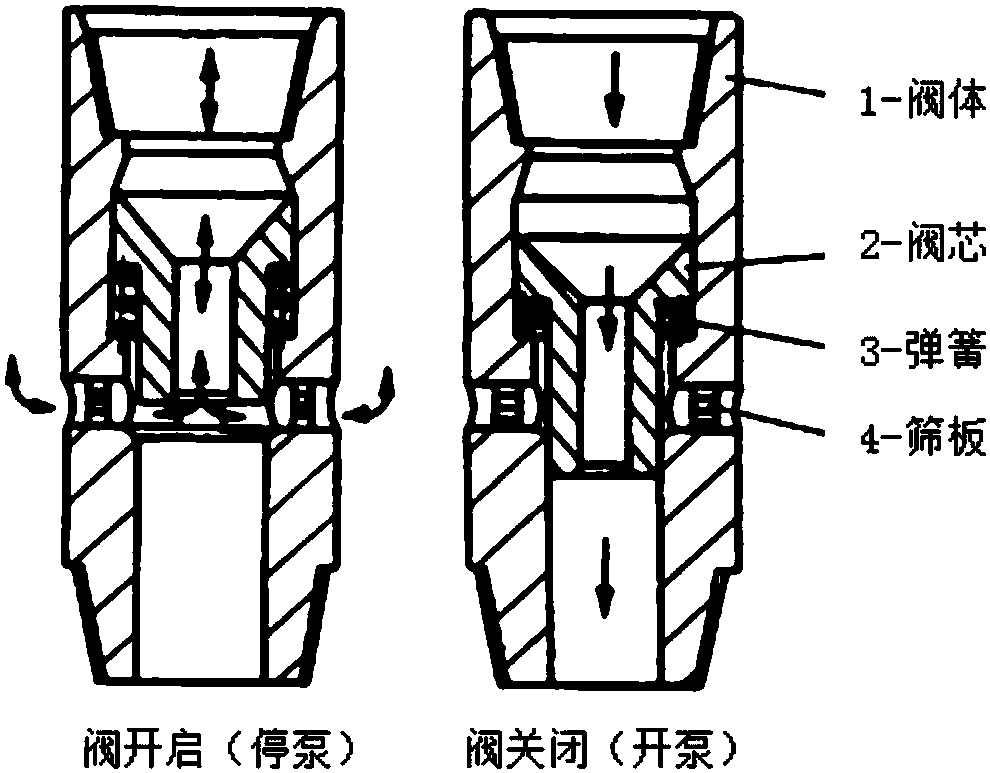
[0074] Such as figure 2 As shown, a screw drilling tool bypass valve with a large displacement flow diversion function includes a valve body 1, a primary valve core 2 and a secondary valve core 9 are arranged inside the valve bod...


PUM


Abstract

The invention discloses a screw drill tool by-pass valve with a large displacement flow dividing function and a using method thereof. The screw drill tool by-pass valve comprises a valve body. The interior of the valve body is provided with a first-level valve core and a second-level valve core. A first-level spring is arranged between the first-level valve core and the second-level valve core. Asecond-level spring is arranged between the second-level valve core and a valve seat. The rigidity of the second-level spring is larger than that of the first-level spring. An inner by-pass hole is formed in the first-level valve core. An outer by-pass hole is formed in the valve body. When the flow pressure in a drilling-fluid fluid channel disappears, the inner by-pass hole communicates with theouter by-pass hole; and an inner flow dividing hole is formed in the second-level valve core, an outer flow dividing hole is formed in the valve body, and when the flow pressure in the drilling-fluidfluid channel is increased to the boundary value, the inner flow dividing hole communicates with the outer flow dividing hole. According to the screw drill tool by-pass valve with the large displacement flow dividing function and the using method thereof, a screw drill tool is allowed to adopt large displacement for circulation and drilling, the rock carrying efficiency at a large size well section, a highly-deviated well section and a horizontal section are improved advantageously, the drilling risk is reduced, and the drilling speed is increased.

Description

technical field [0001] The invention relates to the field of petroleum drilling engineering, in particular to the design and application of a screw drilling tool, in particular to a screw drilling tool bypass valve with large displacement flow diversion and a use method thereof. Background technique [0002] The screw drilling tool is the most commonly used downhole power drilling tool in the field of drilling engineering. The main components include a bypass valve assembly, a motor assembly, a cardan shaft assembly, and a transmission shaft assembly. Among them, the basic structure and working principle of the bypass valve assembly are as follows: figure 1 shown. When the drilling pump is working normally, the drilling fluid pressure forces the valve core to move downward, causing the spring to compress and close the channel on the valve body (the built-in sieve plate filters foreign matter), and the screw drilling tool can circulate the drilling fluid or drill normally. ...

Claims


Application Information

Patent Timeline
Patent Type & Authority Applications(China)
IPC IPC(8): E21B21/10G06F17/50
CPCE21B21/103G06F30/17E21B21/08E21B34/10E21B2200/06
Inventor 史玉才范致斌管志川刘永旺杨卫星滕志想付成林苗在强
Owner CHINA UNIV OF PETROLEUM (EAST CHINA)
Why Eureka
Try Eureka