
Structure for enhancing ion beam focusing of magnetic focusing type hall thruster and design method of structure thereof

A technology of Hall thruster and ion beam focusing, which is applied in the direction of utilizing plasma, reverse thrust device, mechanical equipment, etc., and can solve the problems of focusing ion beam damage and so on

Active Publication Date: 2018-06-15
HARBIN INST OF TECH
View PDF4 Cites 6 Cited by
  • Summary
  • Abstract
  • Description
  • Claims
  • Application Information

AI Technical Summary

Problems solved by technology

[0004] The purpose of the present invention is to solve the problem that the focused ion beam will be destroyed by an external field, thereby providing a structure for enhancing the ion beam focus of a magnetically focused Hall thruster and a design method for the structure

Method used


Image

  • Structure for enhancing ion beam focusing of magnetic focusing type hall thruster and design method of structure thereof
  • Structure for enhancing ion beam focusing of magnetic focusing type hall thruster and design method of structure thereof
  • Structure for enhancing ion beam focusing of magnetic focusing type hall thruster and design method of structure thereof

Examples


specific Embodiment approach 1

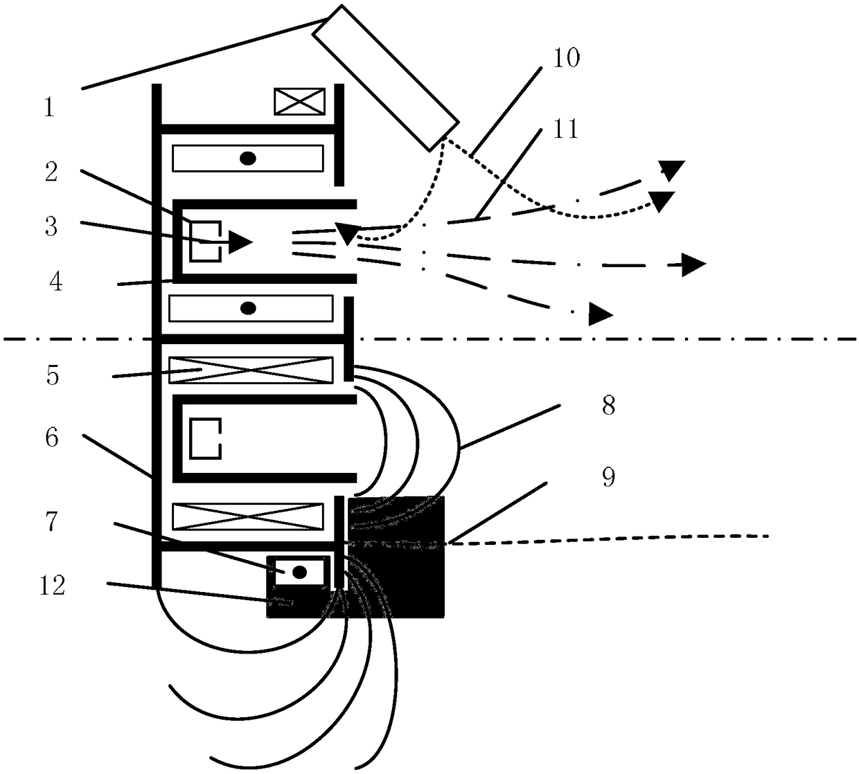
[0020] Specific implementation mode one: combine figure 1 Describe this embodiment in detail, a structure for enhancing the ion beam focusing of a magnetically focused Hall thruster described in this embodiment, constructing a magnetic field in the external field of the Hall thruster, and the magnetic field of the external field and the internal coil of the Hall thruster The magnetic interface of the formed magnetic field is straight, and the cathode hole is located in the inner magnetic mirror area. The specific method of constructing the magnetic field in the external field of the Hall thruster is as follows: setting a coil in the external field of the Hall thruster, and the current direction of the coil is opposite to the current direction of the inner coil of the Hall thruster.

[0021] By induction, the physical essence of the external field is summarized as the active driving ExB discharge of electron beam and ion beam separation. Here we can preliminarily see two facto...

specific Embodiment approach 2

[0033] Specific implementation mode two: combination figure 1 and figure 2Describe this embodiment in detail, a method for designing a structure for enhancing the ion beam focusing of a magnetically focused Hall thruster described in the first embodiment, the method is realized by setting a coil with a reverse current in the external field The magnetic field boundary, the inner magnetic mirror area is located in the straight magnetic interface, and then the installation position of the cathode hole is determined according to the position of the magnetic interface, specifically:

[0034] Step 1. Select the position range of the coil located in the external field through simulation to obtain an alternative position library: add coils with reverse currents at different positions in the external field to ensure that the magnitude of the excitation current parallel to the magnetic interface and the central axis is different , that is to ensure that the magnetic interface is strai...


PUM


Abstract

The invention relates to a structure for enhancing an ion beam focusing of a magnetic focusing type hall thruster and a design method of the structure thereof, and relates to the field of spaceflightelectric propulsion hall thruster beam focusing control, and aims to solve the problem that the focused ion beam can be damaged by an external field. A magnetic field is constructed in the external field of the hall thruster, a magnetic partition interface of the magnetic field formed by the magnetic field of the outer field and the magnetic field formed by an inner coil of the hall thruster is ofa straight cylinder type, and a cathode small hole is located in the inner magnetic mirror area. According to the invention, the radial dispersion of a passive plasma beam can be effectively restrained, so that the effect of beam focusing is enhanced.

Description

technical field [0001] The invention relates to the field of beam focusing control of space electric propulsion Hall thrusters. Background technique [0002] The Hall thruster is an aerospace propulsion device that relies on ejecting high-speed ion beams to obtain reverse thrust. The higher the ion ejection speed, the more concentrated and straight the beam, and the higher the efficiency of generating reverse thrust. However, due to the inherent nature of plasma that tends to diffuse, the actual ejected ion beam is divergent, which causes a series of problems. First of all, a considerable part of the ions will hit the inner wall of the thruster before flying out of the thruster, wasting ions, generating a lot of heat, and quickly corroding the inner wall of the thruster. The ions flying out of the thrusters can bombard and damage other parts of the satellite. Even if the ions manage to fly away from the satellite, they spread into a plasma wake. The more divergent the ion...

Claims


Application Information

Patent Timeline
IPC IPC(8): F03H1/00
CPCF03H1/0081F03H1/0075
Inventor 于达仁孟天航宁中喜
Owner HARBIN INST OF TECH
Learn More