Solar energy installation equipment
A technology for installing equipment and solar energy, which is applied in the field of solar energy, can solve the problems of not being able to bring more convenience to users, and not being able to have practicality, and achieve the effects of saving time and energy, good shock absorption effect, and convenient use
- Summary
- Abstract
- Description
- Claims
- Application Information
AI Technical Summary
Problems solved by technology
Method used
Image

Examples
Embodiment Construction
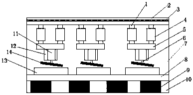
[0012] The following will clearly and completely describe the technical solutions in the embodiments of the present invention with reference to the accompanying drawings in the embodiments of the present invention. Obviously, the described embodiments are only some, not all, embodiments of the present invention. Based on the embodiments of the present invention, all other embodiments obtained by persons of ordinary skill in the art without making creative efforts belong to the protection scope of the present invention.
[0013] refer to figure 1 , a kind of solar energy installation equipment, comprises device main body 7, and base 10 is installed on the lower end of device main body 7, and shock-absorbing device 9 is installed in the cavity of base 10, and transmission device 8 is installed in the cavity lower end of device main body 7, and transmission device 8 The upper end of the drive device 2 is equipped with a placement table 13, the upper end of the inner cavity of the...
PUM
 Abstract
Description
Claims
Application Information
PatSnap Eureka turns technology decisions into work you can execute. Powered by our Innovation Knowledge Graph, it runs expert workflows across engineering, life sciences, materials and intellectual property. Get your review-ready output in minutes.


