
Common-optical-path laser heterodyne interference method roll angle high-precision measuring device and method

A technology of laser heterodyne interference and measuring device, applied in measuring device, using optical device, instrument, etc., can solve the problems of inaccurate measurement, measurement influence, difficulty in roll angle measurement, etc. The effect of reducing the distance difference

Active Publication Date: 2018-06-15
XI AN JIAOTONG UNIV
View PDF7 Cites 18 Cited by
  • Summary
  • Abstract
  • Description
  • Claims
  • Application Information

AI Technical Summary

Problems solved by technology

[0003] For the roll angle error, because the error direction is perpendicular to the direction of the measuring beam, no additional optical path difference can be introduced, so the measurement of the roll angle is relatively difficult. At present, it is still in a research and exploration stage at home and abroad.
[0004] In the existing laser heterodyne interferometry method, due to the large optical path difference between the reference light and the measuring light, in the measurement of the large stroke guide rail, the environmental factors will have a serious impact on the measurement and cannot be measured accurately

Method used


Image

  • Common-optical-path laser heterodyne interference method roll angle high-precision measuring device and method
  • Common-optical-path laser heterodyne interference method roll angle high-precision measuring device and method
  • Common-optical-path laser heterodyne interference method roll angle high-precision measuring device and method

Examples


Embodiment Construction

[0030] The present invention will be further described in detail below in conjunction with the accompanying drawings, which are explanations rather than limitations of the present invention.

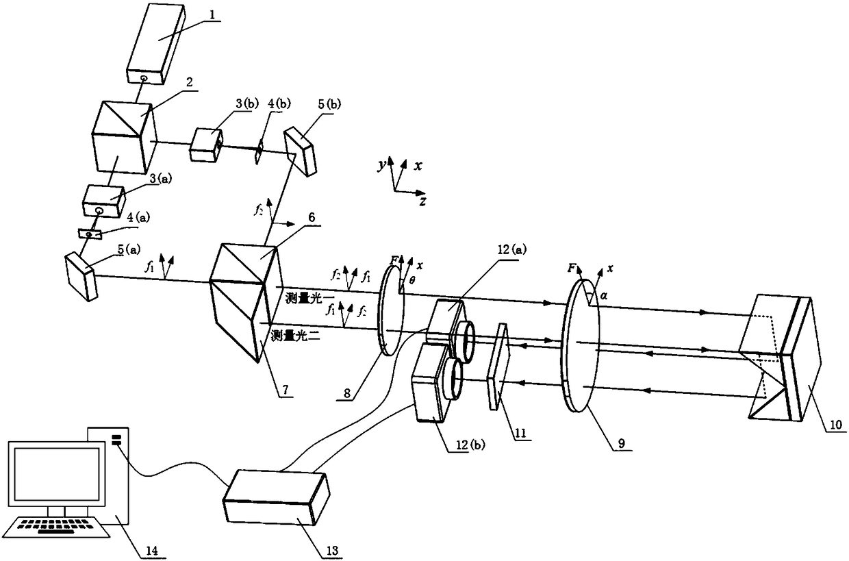
[0031] see figure 1 , a common optical path laser heterodyne interferometry roll angle high-precision measurement device, characterized in that it includes a single-frequency stabilized laser 1, a depolarization beamsplitter prism 2 arranged on the output optical path of the single-frequency stabilized laser 1, and a polarization beamsplitter prism 6 and a rectangular prism 7; the first AOM 3a and the first reflection mirror 5a are arranged in turn on the transmission optical axis of the depolarization beam splitter prism 2; the first reflection mirror 5a is used for the first AOM 3a A diffracted light is reflected to the polarization splitter prism 6; the second acousto-optic modulator 3b and the second reflection mirror 5b are sequentially arranged on the reflection axis of the depolar...


PUM


Abstract

The invention belongs to the field of photoelectric measurement of a roll angle, in particular to a common-optical-path laser heterodyne interference method roll angle high-precision measuring device.The measuring device includes a single frequency stabilized laser, a depolarization beam splitting prism, a polarization beam splitting prism, and a right angle prism; an acousto-optic modulator anda reflector are sequentially arranged on the transmission optical axis and the reflection optical axis of the depolarization beam splitting prism; the second exit surface of the polarization beam splitting prism is sequentially provided with a quarter wave plate, a half-wave plate and a reflector, and a polarization analyzer is further arranged on the reflection optical axis of the reflector, a first photoelectric detector and a second photoelectric detector are arranged in the exit direction of the polarization analyzer; the first photoelectric detector and the second photoelectric detector are connected with a phase difference detector, and the phase difference detector is connected with a computer. The two measuring light rays in the measuring device are opposite to the phase shift generated by the same rolling, the measuring resolution is improved, the optical path difference of the two light beams is small, the influence of environmental factors is small, and the measurement result is accurate.

Description

technical field [0001] The invention belongs to the field of photoelectric measurement of roll angle, and specifically relates to a high-precision roll angle measurement device and method of common optical path laser heterodyne interferometry. Background technique [0002] Precision guide rails play an important role in manufacturing, aerospace and other industries. There are six geometric errors in the linear guide, namely: positioning error, two straightness errors, pitch angle, yaw angle and roll angle. Roll angle error is an important part of the geometric error of high-end machine tools, and its accuracy is one of the important reference indicators to measure the performance of guide rails. Its measurement is the key to product acceptance inspection and error compensation. [0003] For the roll angle error, because the error direction is perpendicular to the direction of the measuring beam, no additional optical path difference can be introduced, so the measurement of ...

Claims


Application Information

Patent Timeline
IPC IPC(8): G01B11/26
CPCG01B11/26
Inventor 王昭齐静雅黄军辉高建民齐红泽
Owner XI AN JIAOTONG UNIV
Learn More