Medical ultrasonic probe sterilizer

A technology of ultrasonic probe and sterilizer, which is applied in the direction of disinfection and irradiation, and can solve the problems of broken filter lenses, reduced disinfection effect, and limited disinfection and sterilization area, so as to prevent the accumulation of dust, increase the disinfection area, and improve the disinfection effect Good results

Pending Publication Date: 2018-06-19
HUNAN NEWBEA TECH CO LTD
View PDF0 Cites 3 Cited by
  • Summary
  • Abstract
  • Description
  • Claims
  • Application Information

AI Technical Summary

Problems solved by technology

[0006] In the prior art, there is a B-ultrasound probe sterilizer that directly places the B-ultrasound probe on the filter lens, and only sets an ultraviolet generating device at the bottom of the sterilizer to carry out deep ultraviolet disinfection. The technology of carrying out disinfection has following shortcoming: (1) the ultrasonic probe of B is directly placed on the optical filter lens, easily causes the damage of ultrasonic probe of B and the fragmentation of optical filter lens; (2) in addition, ultrasonic probe of B directly contacts with sterilizer, There is pollution of the filter lens, which reduces the light transmittance and reduces the disinfection effect; (3) the ultraviolet generating device in the disinfection component is located at the bottom of the disinfection chamber of the probe, and the direction of ultraviolet radiation is single, and the disinfection and sterilization area is limited, so it cannot be used in all directions No dead angle disinfection; (4) The opening of the sterilizer is upward, which is easy to cause dust accumulation and reduce the disinfection effect

Method used


Image

  • Medical ultrasonic probe sterilizer
  • Medical ultrasonic probe sterilizer
  • Medical ultrasonic probe sterilizer

Examples


Embodiment 1

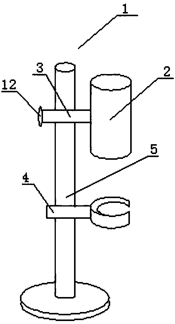
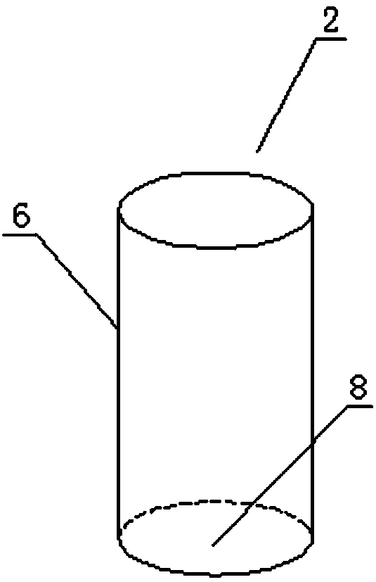
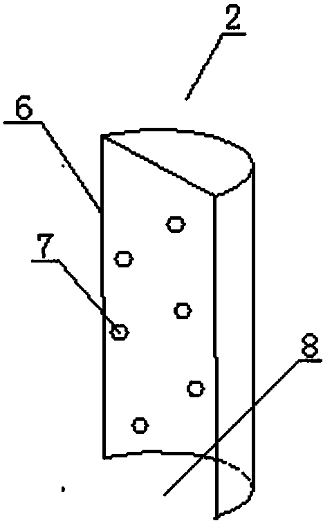
[0030] Such as figure 1 , figure 2 , image 3 As shown, a medical ultrasonic probe sterilizer 1 includes a sterilizer body 2, a body fixing frame 3, a probe fixing frame 4, and a sterilizer support rod 5; the sterilizer body 2 includes a cover body 6, a deep ultraviolet light source 7, The cover body 6 is provided with an opening 8 and the direction of the opening 8 is downward, the size of the opening 8 is suitable for the probe to enter and exit the cover body 6, and the inner space of the cover body 6 is suitable for placing the deep ultraviolet light source 7 and the probe, And it is possible to prevent the probe from contacting the inner wall of the cover body 6 and the deep ultraviolet light source 7 after the probe is inserted. The deep ultraviolet light source 7 is installed on the inner surface of the cover body 6 and is multi-point distributed. The deep ultraviolet light source 7 The distribution of the probe can realize that after the probe is inserted into the c...


PUM

PropertyMeasurementUnit
wavelengthaaaaaaaaaa

Abstract

The invention relates to a medical ultrasonic probe sterilizer. The medical ultrasonic probe sterilizer comprises a sterilizer body, a body fixed mount, a probe fixed mount, and a sterilizer support bar; the sterilizer body comprises a cover body and a DUV light source, an opening is arranged at the cover body, an opening direction towards downwardly, a size of the opening is suitable for introducing a probe in and out of the cover body, a space in the cover body is suitable for placing the DUV light source and the probe, after the probe is set, the probe is not contacted with an inner wall ofthe cover body and the DUV light source, and the DUV light source is arranged at an inner surface of the cover body and realizes multi-point distribution; the sterilizer support bar is vertically arranged; one end of the body fixed mount is connected with the sterilizer body, and the other end is connected with the sterilizer support bar; one end of the probe fixed mount is used for fixing the probe, and the other end is connected with the sterilizer support bar and is positioned at the lower part of the body fixed mount. The medical ultrasonic probe sterilizer has the advantages of dust prevention, safety and no side effect for medical workers, omnibearing no-blind angle disinfection, no damage for the probe, detachable performance of integral body, simple structure, low cost, and good disinfection effect.

Description

technical field [0001] The invention relates to a medical probe sterilizer, in particular to a medical ultrasonic probe sterilizer. Background technique [0002] Medical probes are widely used in medical diagnosis and treatment equipment, especially in ultrasonic diagnostic equipment, the ultrasonic probe is an indispensable and one of the most important components, during the inspection process, the ultrasonic probe directly contacts the patient's body through the coupling agent , is a component with a high risk of contamination and infection. Disinfection of probes in compliance with national and local standards is an essential step for every patient before being examined. [0003] Deep ultraviolet light refers to ultraviolet light with a wavelength between 200 nm and 350 nm. In the medical field, ultraviolet light with a wavelength between 240 nm and 280 nm is widely used in disinfection of air and object surfaces. [0004] Deep ultraviolet light sources refer to device...

Claims


Application Information

Patent Timeline
Patent Type & Authority Applications(China)
IPC IPC(8): A61L2/10
CPCA61L2/10A61L2202/11A61L2202/24
Inventor 聂新章黄红波谭钢钢
Owner HUNAN NEWBEA TECH CO LTD
Why Eureka
Try Eureka