An energy-saving and environment-friendly bio-glue curtain cabinet and its waste gas waste treatment method

An energy-saving, environmentally friendly and bio-adhesive technology, applied in the field of water curtain cabinets, can solve problems such as difficulty in cleaning and inability to guarantee secondary pollution treatment.

Active Publication Date: 2020-07-03
武汉斯特蓝科技发展有限公司
View PDF8 Cites 0 Cited by
  • Summary
  • Abstract
  • Description
  • Claims
  • Application Information

AI Technical Summary

Problems solved by technology

[0002] Generally, in the purification process of the water curtain cabinet, only clean water is used for water adsorption treatment, and the use of water treatment can only simply rely on the adhesion of water and the hydrophilicity of organic pollutants to adhere the pollutants falling on the surface of the water body. The attached organic waste residues are all floating on the surface of the water body, which is difficult to clean up, and the secondary pollution caused by its volatilization cannot be guaranteed to be treated.

Method used


Image

  • An energy-saving and environment-friendly bio-glue curtain cabinet and its waste gas waste treatment method
  • An energy-saving and environment-friendly bio-glue curtain cabinet and its waste gas waste treatment method
  • An energy-saving and environment-friendly bio-glue curtain cabinet and its waste gas waste treatment method

Examples


Embodiment 1

[0051] Embodiment 1: as Figure 4 As shown, when the front activated carbon adsorption purification chamber 10, the photolysis sterilization chamber 11, the rear activated carbon adsorption purification chamber 12, the muffler chamber 13 and the exhaust duct 14 are combined and arranged on the cabinet body 1, the front activated carbon adsorption purification chamber 10 It is arranged above the gas static pressure chamber 8 and communicates with the gas static pressure chamber 8. The photolysis sterilization chamber 11 is arranged above the front activated carbon adsorption purification chamber 10 and communicates with the front activated carbon adsorption purification chamber 10. The rear activated carbon adsorption purification chamber 12 It is arranged above the photolysis sterilization chamber 11 and communicates with the photolysis sterilization chamber 11. The anechoic chamber 13 is arranged above the rear activated carbon adsorption purification chamber 12 and communicat...

Embodiment 2

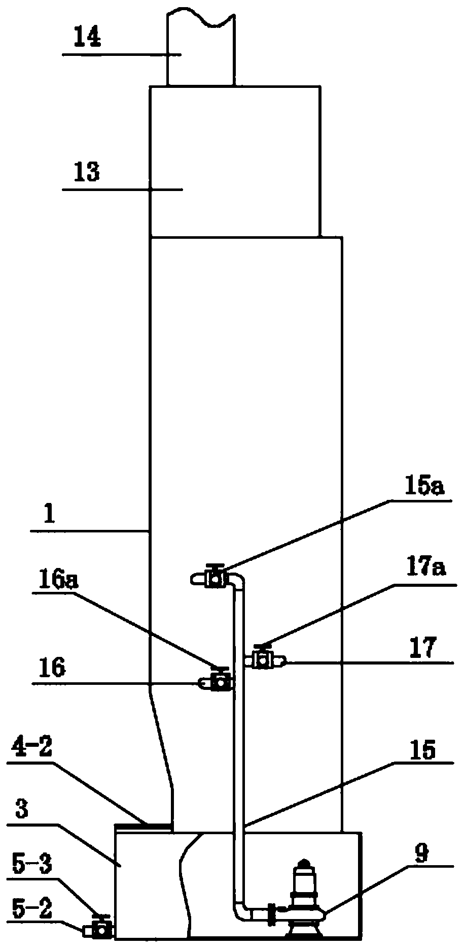
[0052] Embodiment 2: as Figure 5 As shown, when the front activated carbon adsorption purification chamber 10, the photolysis sterilization chamber 11, the rear activated carbon adsorption purification chamber 12, the muffler chamber 13 and the exhaust duct 14 are combined and arranged outside the cabinet body 1, the front activated carbon adsorption purification chamber 10 The first pipeline 21 communicates with the gas static pressure chamber 8, the photolysis sterilizing chamber 11 is arranged above the front activated carbon adsorption purification chamber 10 and communicates with the front activated carbon adsorption purification chamber 10, and the rear activated carbon adsorption purification chamber 12 is arranged on the photolysis chamber. Above the sterilizing chamber 11 and communicate with the photolysis sterilizing chamber 11, the anechoic chamber 13 is arranged above the rear activated carbon adsorption purification chamber 12 and communicates with the rear activ...

Embodiment 3

[0053] Embodiment 3: as Figure 6 As shown, when the front activated carbon adsorption purification chamber 10, the photolysis sterilization chamber 11, the rear activated carbon adsorption purification chamber 12, the muffler chamber 13 and the exhaust duct 14 are all independently arranged outside the cabinet body 1, the front activated carbon adsorption purification chamber 10 The second pipeline 22 communicates with the gas static pressure chamber 8, the photolysis sterilization chamber 11 communicates with the front active carbon adsorption purification chamber 10 through the third pipeline 23, and the rear activated carbon adsorption purification chamber 12 communicates with the photolysis sterilization chamber through the fourth pipeline 24. 11 communicates, the muffler chamber 13 communicates with the rear activated carbon adsorption purification chamber 12 through the fifth pipeline 25, and the exhaust duct 14 communicates with the muffler chamber 13.

[0054] Such as...


PUM


Abstract

The invention discloses an energy-saving and environment-protection type biological glue water curtain cabinet and a waste gas and waste residue treatment method thereof. The energy-saving and environment-protection type biological glue water curtain cabinet is characterized in that a biological glue waste gas residue-blocking dust-removing chamber is arranged in a cabinet, a two-stage wind inletflow guide plate, a two-stage glue distribution diversion device, a two-stage biological glue waste gas residue-blocking wind distribution plate, a two-stage glue distribution diversion device, a two-stage glue guide groove and a residual glue collection device are arranged in the biological glue waste gas residue-blocking dust-removing chamber, each stage of the glue guide groove is connected toeach stage of the glue distribution diversion device, and each stage of the glue distribution diversion device is correspondingly connected to each stage of the biological glue waste gas residue-blocking wind distribution plate. The treatment method comprises: purifying large-particle waste residue, purifying fine-particle waste residue, carrying out photolysis sterilization and discharge on wastegas, purifying and recycling a biological glue, and other steps. According to the present invention, the energy-saving and environment-protection type biological glue water curtain cabinet has advantages of zero discharge, zero pollution and significant purification effect, and uses the biological glue to replace the clear water so as to perform circulation purification treatment.

Description

technical field [0001] The invention relates to the technical field of water curtain cabinets, in particular to an energy-saving and environment-friendly bio-glue water curtain cabinet and a method for treating waste gas and residue thereof. Background technique [0002] Generally, in the purification process of the water curtain cabinet, only clean water is used for water adsorption treatment, and the use of water treatment can only simply rely on the adhesion of water and the hydrophilicity of organic pollutants to adhere the pollutants falling on the surface of the water body. The attached organic waste residues are all floating on the surface of the water body, which is difficult to clean up, and the secondary pollution caused by its volatilization cannot be guaranteed to be treated. Contents of the invention [0003] The object of the present invention is to provide an energy-saving and environment-friendly bio-glue water curtain cabinet and a method for treating wast...

Claims


Application Information

Patent Timeline
Patent Type & Authority Patents(China)
IPC IPC(8): B01D50/00B01D53/74
CPCB01D50/00B01D53/74B01D2247/04B01D2257/91
Inventor 季茂顺
Owner 武汉斯特蓝科技发展有限公司
Why Eureka
Try Eureka