Energy tower and heat pump system thereof
A technology of energy tower and sprinkler system, applied in the direction of heat storage equipment, indirect heat exchanger, heat exchanger type, etc., to achieve the effect of reducing charging amount, increasing heat exchange area, and compact overall size
- Summary
- Abstract
- Description
- Claims
- Application Information
AI Technical Summary
Problems solved by technology
Method used
Image
Examples
Embodiment 1
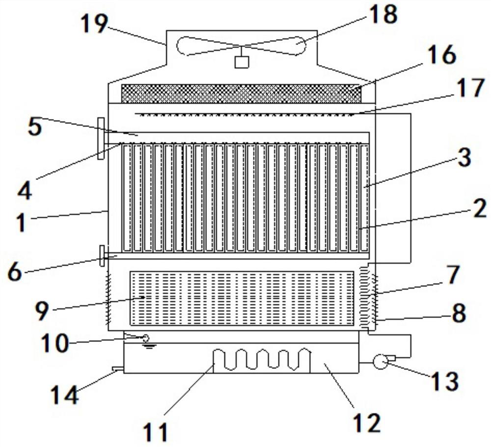
[0033] Such as figure 1 The design idea and structure of an energy tower shown in this technical scheme are roughly the same as the implementation scheme of a phase change energy tower and its heat exchange method described in the Chinese invention patent with the publication number CN110360852A previously applied. For details, please refer to The content of the patent application document is different in that the heat exchange tube in the previous energy tower is changed to further improve its heat exchange efficiency, as follows:
[0034] The energy tower includes a tower body 1, which is provided with a heat exchange assembly for sealing and conveying refrigerant, and a spray system using a phase change medium as a fluid; the spray system includes a heat exchange assembly The sprayer 17 above and the spraying direction is toward the heat exchange tube, and the liquid storage tank 12 arranged below the heat exchange assembly for receiving the phase change medium; the liquid stor...
Embodiment 2
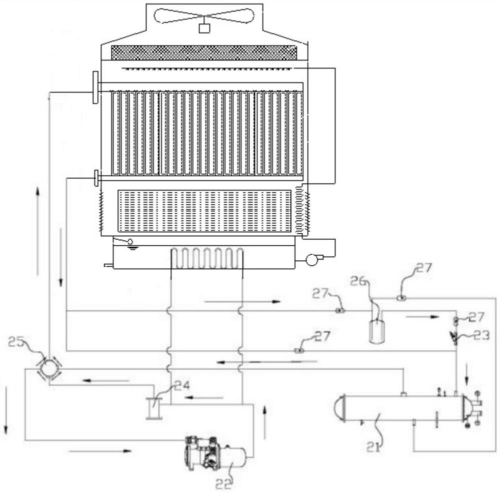
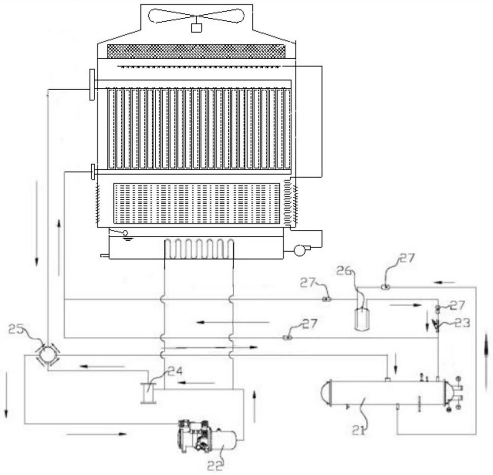
[0052] This embodiment is a heat pump system based on the energy tower in Embodiment 1. Therefore, this embodiment adopts the specific energy tower in Embodiment 1 for implementation. Specifically, the heat pump system includes the energy tower described in Embodiment 1 and a closed refrigerant circulating circuit, the heat exchange assembly is connected to the closed refrigerant circulating circuit, and the closed refrigerant circulating circuit further includes a heat exchanger 21, The heat exchange direction of the refrigerant in the heat exchanger 21 is opposite to that in the heat exchange tube of the energy tower.
[0053] The liquid collecting pipe 6 is the liquid inlet and outlet ends, and the gas collecting pipe 5 is the gas inlet and outlet ends; the refrigerant cycle closed circuit also includes a compressor 22, a throttling device 23, and an oil separator 24. The compressor 22 and the oil separator 24 , The gas collecting pipe 5, the liquid collecting pipe 6, the thro...
Embodiment 3
[0055] This embodiment is based on the heat exchange method adopted in the heat pump system with energy tower in the second embodiment, so this embodiment adopts the heat pump system in the above-mentioned embodiment 2 for implementation. For specific details, please refer to the applicant's description of the implementation scheme of a phase-change energy tower and its heat exchange method in the Chinese invention patent with publication number CN110360852A, which will not be repeated here.
[0056] Summer mode (e.g. figure 2 Shown): The refrigerant gas is compressed by the compressor 22 and then enters the oil separator 24 for oil separation, flows through the four-way valve 25, and then the refrigerant gas enters the gas collecting pipe 5; the spray system runs, and the phase change medium passes through the sprayer 17 Sprayed on the surface of the heat exchange plate 2, the phase change medium forms a water film on the surface of the heat exchange plate 2, and absorbs heat th...
PUM
 Abstract
Description
Claims
Application Information
 - R&D
- Intellectual Property
- Life Sciences
- Materials
- Tech Scout
- Unparalleled Data Quality
- Higher Quality Content
- 60% Fewer Hallucinations
Browse by: Latest US Patents, China's latest patents, Technical Efficacy Thesaurus, Application Domain, Technology Topic, Popular Technical Reports.
© 2025 PatSnap. All rights reserved.Legal|Privacy policy|Modern Slavery Act Transparency Statement|Sitemap|About US| Contact US: help@patsnap.com


