A bedding cement device for building walls

A technology for cement installation and wall laying, which is applied in cement mixing installations, buildings, building structures, etc., can solve problems such as low paving efficiency and high labor intensity, and achieve the effects of preventing clumping, reducing labor intensity, and moving smoothly.

Active Publication Date: 2022-04-08
天长市振业建设工程有限公司
View PDF6 Cites 0 Cited by
  • Summary
  • Abstract
  • Description
  • Claims
  • Application Information

AI Technical Summary

Problems solved by technology

[0005] In order to overcome the disadvantages of high labor intensity and low bedding efficiency in the way that architects manually use trowels to cover cement slurry, the technical problem to be solved by the present invention is to provide a method that can reduce the labor intensity of builders and improve the efficiency of bedding cement. Slurry-efficient blanket cement installations for building masonry

Method used


Image

  • A bedding cement device for building walls
  • A bedding cement device for building walls
  • A bedding cement device for building walls

Examples


Embodiment 1

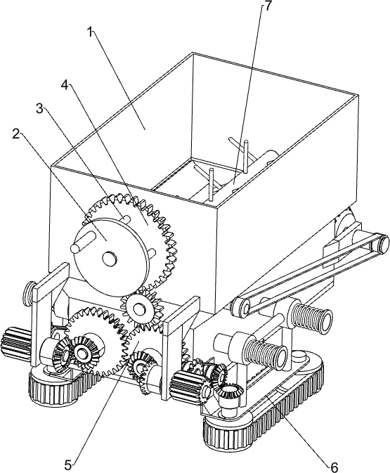
[0022] A bedding cement device for building walls, such as Figure 1-4 As shown, it includes a material storage box 1, a hand pan 2, a first connecting rod 3, a first gear 4, a spreading mechanism 5 and an auxiliary moving mechanism 6, and the front side of the material storage box 1 is rotatably connected with the first gear 4 , the front side of the first gear 4 is connected with a plurality of first connecting rods 3 evenly spaced along the circumferential direction, the front ends of the plurality of first connecting rods 3 are connected with a hand pan 2, and the material storage box 1 is equipped with a paving material Mechanism 5, the spreading mechanism 5 is connected with the transmission of the first gear 4, and the auxiliary moving mechanism 6 is installed on the spreading mechanism 5.

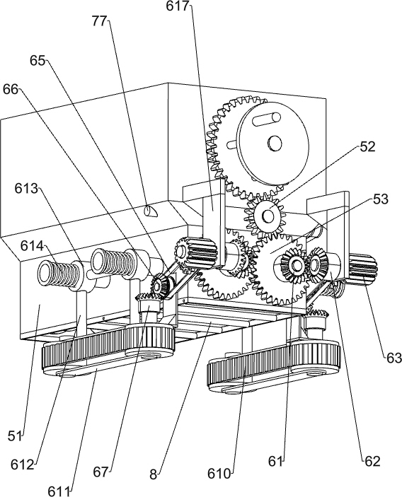
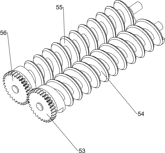
[0023] The spreading mechanism 5 includes a spreading box 51, a second gear 52, a third gear 53, a first screw shaft 54, a second screw shaft 55 and a fourth gear 56, and the front ...

Embodiment 2

[0027] On the basis of Example 1, such as Figure 1-3 Shown, also include stirring mechanism 7, and stirring mechanism 7 includes second transmission belt group 71, stirring bar 72, the 5th bevel gear 73, the 6th bevel gear 74, connecting shaft 75, the 3rd transmission belt group 76, dial The material rod 77 and the fixed plate 78 are connected with the stirring rod 72 in a rotating manner on the material storage box 1, and the second transmission belt group 71 is connected between the rear end of the stirring rod 72 and the rear end of the second screw shaft rod 55, and the first screw shaft The rear end of the rod 54 is connected with the fifth bevel gear 73, and the rear side of the right side of the spreading box 51 is connected with a fixed plate 78. The fixed plate 78 is connected with a connecting shaft 75 in a rotating manner, and the left end of the connecting shaft 75 is connected with a sixth cone. Gear 74, the 6th bevel gear 74 and the 5th bevel gear 73 meshes, on ...


PUM


Abstract

The invention relates to a bedding cement device, in particular to a bedding cement device for building walls. The technical problem to be solved by the present invention is how to provide a bedding cement device for building walls that can reduce the labor intensity of builders and improve the efficiency of bedding cement slurry. In order to solve the above-mentioned technical problems, the present invention provides such a bedding cement device for building walls, comprising: a material storage box, one side of which is rotatably connected to a first gear; a first connecting rod, on which a first gear is connected A connecting rod; a hand-operated plate, the hand-operated plate is connected to the first connecting rod; a material-spreading mechanism, the material-spreading mechanism is installed on the material storage box, and the material-spreading mechanism is connected with the first gear through transmission. The counterclockwise rotation of the first gear of the device can drive the material spreading mechanism to work, the material spreading mechanism can cover the cement slurry on the bricks, and the material spreading mechanism can also drive the auxiliary moving mechanism to work.

Description

technical field [0001] The invention relates to a bedding cement device, in particular to a bedding cement device for building walls. Background technique [0002] When building a wall, the builder needs to spread the cement slurry on the bricks that have been laid, and then take another brick and place it on the cement slurry that has been laid. At present, it is generally the builder who builds the cement slurry manually. When the builder manually builds the cement slurry, he holds the cement bucket in one hand, and the other hand holds the trowel to scoop up the cement slurry in the cement bucket, and then pours the cement slurry on the trowel. On the bricks that have been built, the builder needs to frequently scoop up and pour the cement slurry, so the labor intensity of the builder is relatively high, and the efficiency of covering the cement slurry is relatively low. [0003] Therefore need to research and develop a kind of labor intensity that can alleviate the buil...

Claims


Application Information

Patent Timeline
Patent Type & Authority Patents(China)
IPC IPC(8): E04G21/20B28C5/14
CPCE04G21/20B28C5/14
Inventor 陈梓斌
Owner 天长市振业建设工程有限公司
Why Eureka
Try Eureka