
Faraday probe

A probe and flange surface technology, applied in the field of Faraday probes, can solve the problems of low measurement accuracy of Faraday probes

Active Publication Date: 2018-06-19
BEIHANG UNIV
View PDF5 Cites 6 Cited by
  • Summary
  • Abstract
  • Description
  • Claims
  • Application Information

AI Technical Summary

Problems solved by technology

[0006] The purpose of the present invention is to provide a Faraday probe to solve the technical problem that the measurement accuracy of the existing Faraday probe is low

Method used


Image

  • Faraday probe
  • Faraday probe
  • Faraday probe

Examples


Embodiment Construction

[0027] It should be noted that the embodiments of the present invention and the features in the embodiments can be combined with each other if there is no conflict. Hereinafter, the present invention will be described in detail with reference to the drawings and in conjunction with the embodiments.

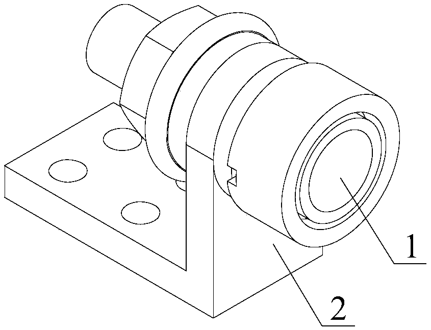
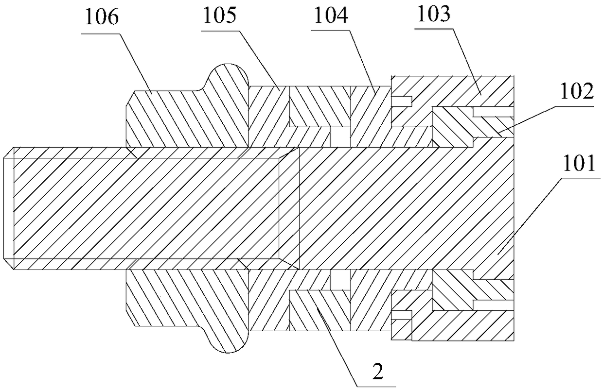
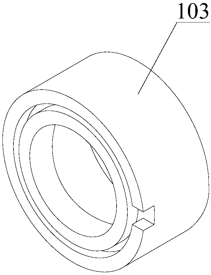
[0028] figure 1 Is a schematic structural diagram of a Faraday probe provided by an embodiment of the present invention; figure 2 Is a schematic diagram of a transverse cross-sectional structure of a Faraday probe provided by an embodiment of the present invention; image 3 It is a schematic diagram of the structure of the guard ring in the Faraday probe provided by an embodiment of the present invention.

[0029] Such as figure 1 - image 3 As shown, the embodiment of the present invention provides a Faraday probe, including: a Faraday probe body 1; the Faraday probe body 1 includes: a collection ring 101, a collection protection insulating device 102, and a protection ring 103; the...


PUM


Abstract

The invention discloses a Faraday probe, relates to the technical field of aerospace instruments, and aims at solving the technical problems of low measurement accuracy of the present Faraday probe. The Faraday probe comprises a Faraday probe body. The Faraday probe body comprises a collection ring, a collection protection insulation device and a protection ring. The external side of the collection ring is sleeved by the collection protection insulation device. The external side of the collection protection insulation device is sleeved by the protection ring. The collection protection insulation device and the collection ring are fit in an interference way. The collection protection insulation device and the protection ring are fit in a clearance way.

Description

Technical field [0001] The invention relates to the technical field of aerospace equipment, in particular to a Faraday probe. Background technique [0002] At present, electric thrusters such as ion thrusters and Hall thrusters are widely used in the attitude and orbit control of spacecraft due to their advantages of high specific impulse, long life and low system mass. Accurately obtaining the vacuum plume parameters of electric thrusters is very important for evaluating the performance of electric thrusters and spacecraft. [0003] Among them, the vacuum plume of the electric thruster is plasma, and the beam current density is the basic parameter of the plasma plume flow field. Obtaining the beam current density can not only estimate the number density of charged particles in the flow field, and then estimate the force of the plume on the spacecraft. Thermal effects and sputtering pollution effects can also be used as input and calibration conditions for numerical simulation of ...

Claims


Application Information

Patent Timeline
IPC IPC(8): G01T1/29G01R19/08
Inventor 蔡国飙刘立辉苏杨翁惠焱贺碧蛟
Owner BEIHANG UNIV
Learn More