Inductor and DC-DC converter

A technology of inductor and ground wire, applied in transformer/inductor magnetic core, transformer/inductor cooling, transformer/inductor noise damping, etc., to ensure the effect of insulation and heat dissipation

Active Publication Date: 2018-06-19
MURATA MFG CO LTD
View PDF3 Cites 23 Cited by
  • Summary
  • Abstract
  • Description
  • Claims
  • Application Information

AI Technical Summary

Problems solved by technology

Therefore, there is a possibility of upsizing due to the provision of such a heat-shrinkable insulating structure and conductive coating

Method used


Image

  • Inductor and DC-DC converter
  • Inductor and DC-DC converter
  • Inductor and DC-DC converter

Examples


no. 1 approach

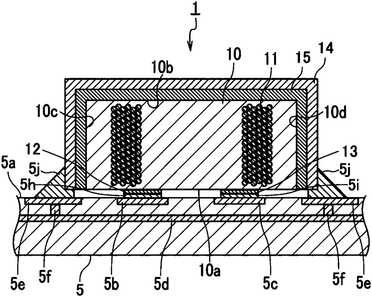
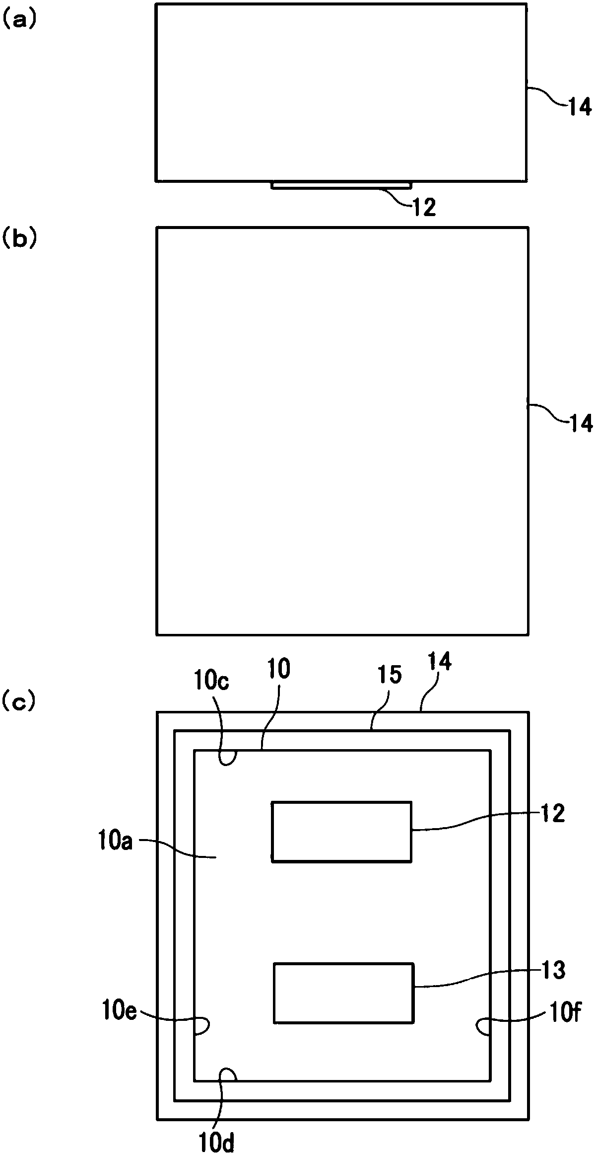
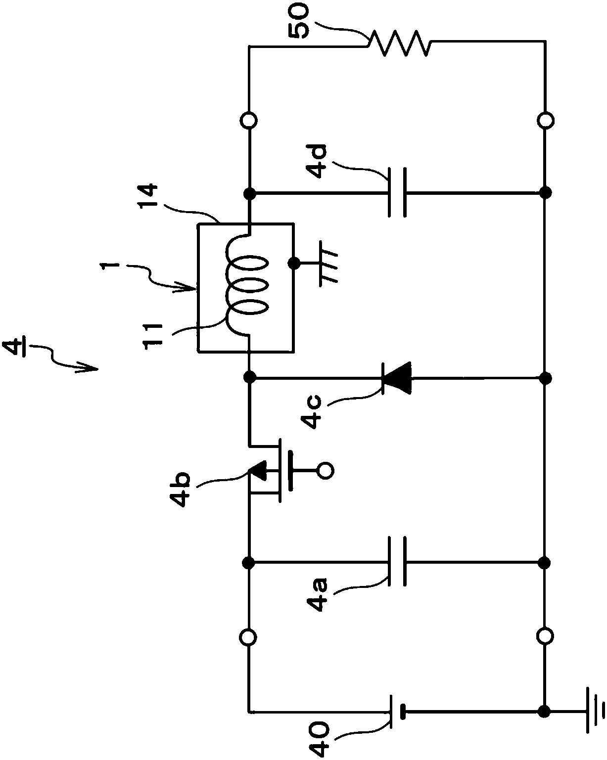
[0028] refer to Figure 1 ~ Figure 3 , the inductor 1 of the first embodiment will be described. figure 1 It is a cross-sectional view schematically showing the structure of the inductor 1 according to the first embodiment. figure 2 It is a figure which shows typically the external appearance of the inductor 1 of 1st Embodiment, (a) is a side view, (b) is a top view, and (c) is a bottom view. image 3 It is a circuit diagram of the DC-DC converter 4 including the inductor 1 of the first embodiment. Furthermore, in figure 1 In the figure, the inductor 1 and a part of the substrate 5 on which the inductor 1 is mounted are shown.

[0029] The inductor 1 is a power inductor used as one of the electronic components of the DC-DC converter 4 . The DC-DC converter 4 including the inductor 1 is mounted on the substrate 5 . Before describing the inductor 1 in detail, refer to image 3 , the DC-DC converter 4 will be described.

[0030]For example, the DC-DC converter 4 steps dow...

no. 2 approach

[0065] refer to Figure 4 and Figure 5 , the inductor 2 of the second embodiment will be described. Figure 4 It is a front view schematically showing the structure of the inductor 2 of the second embodiment. Figure 5 It is a figure which schematically shows the appearance of the inductor 2 of 2nd Embodiment, (a) is a side view, (b) is a top view, (c) is a bottom view. Furthermore, in Figure 4 The inductor 2 and a part (cross section) of the substrate 5 on which the inductor 2 is mounted are shown in FIG.

[0066] Compared with the inductor 1 of the first embodiment, the inductor 2 is different in that an external electrode is provided on a side surface of the core body, and a shield member and an insulating member are not provided on the side surface. The inductor 2 includes the same core body 10 and winding wire 11 as the inductor 1 . In addition, the inductor 2 includes a pair of external electrodes 22 and 23 , a shield member 24 and an insulating member 25 .

[00...


PUM

PropertyMeasurementUnit
thicknessaaaaaaaaaa
thicknessaaaaaaaaaa
magnetic permeabilityaaaaaaaaaa

Abstract

The present invention provides an inductor which has a noise inhibition effect based on a shielding part, guarantees the insulativity and the heat radiation performance between the shielding part anda core body of the inductor and can be made miniature. The inductor (1) comprises the core body (10) made of a metallic magnetic material, a wire wound around the core body, a pair of outer electrodes(12, 13) coupled to respective end portions of the core body, the shielding part 14 arranged so as to cover a top face and three or more side faces of the core body, and an insulating member 15 arranged between the core body and the shielding part and having the thermal conductivity. The thickness of the shielding member is set by applying the electric resistivity and permeability of the shielding part and the frequency of noise desired to be shielded to an expression for determining the depth of a skin of skin effect. The thickness of the insulating member is set according to the breakdown voltage of the insulating member and the voltage with which insulation is desired to be ensured under a use environment of the inductor.

Description

technical field [0001] The present invention relates to an inductor and a DC-DC converter including the inductor. Background technique [0002] The DC-DC converter includes, for example, a switching element, a diode, an inductor (power inductor), a smoothing capacitor, and the like, and steps down or steps up an arbitrary DC voltage to a desired DC voltage. For example, when a DC-DC converter is used as a power supply circuit of an electronic device in an automobile, noise radiated from an inductor or the like of the DC-DC converter may become a problem in AM broadcasting mounted in a car or the like. In order to suppress noise radiated from the inductor, for example, a shield member covering the inductor is used. [0003] However, as the power inductor of the DC-DC converter, for example, a metal composite type inductor (hereinafter, referred to as a "metal composite inductor") that is small and can cope with a large current is used. The core of the metal composite induct...

Claims


Application Information

Patent Timeline
Patent Type & Authority Applications(China)
IPC IPC(8): H01F27/22H01F27/32H01F27/33H02M3/155
CPCH01F27/22H01F27/324H01F27/33H02M3/155H02M1/0064H01F27/363H01F17/04H02M1/44H01F27/292H02M3/156H01F27/29H01F27/24H01F27/2823H02M1/143
Inventor 高辻宽之
Owner MURATA MFG CO LTD
Why Eureka
Try Eureka