Warping machine warp beam transfer robot and control method thereof

A control method and warping machine technology, applied in the direction of program control of manipulators, manipulators, manufacturing tools, etc., can solve the problems of low efficiency of warp beams of warping machines, high labor intensity of workers, and potential safety hazards, and achieve a reasonable and effective control method. order, realize automatic production, and avoid the effect of collision accidents

Inactive Publication Date: 2018-06-22
ZHONGYUAN ENGINEERING COLLEGE
View PDF3 Cites 2 Cited by
  • Summary
  • Abstract
  • Description
  • Claims
  • Application Information

AI Technical Summary

Problems solved by technology

[0003] In view of the deficiencies in the above-mentioned background technology, the present invention proposes a control method for warp beam transfer robots of warping machines, which solves the problems of low efficiency, high labor intensity and potential safety hazards in the warping machine warp beam replacement process in the prior art

Method used


Image

  • Warping machine warp beam transfer robot and control method thereof
  • Warping machine warp beam transfer robot and control method thereof
  • Warping machine warp beam transfer robot and control method thereof

Examples


Embodiment 2

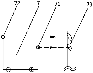
[0025] Embodiment 2, a warp beam transfer robot, the electromagnetic navigation system includes metal wires buried in the walking section 5, and the metal wire is loaded with a guiding frequency, and the warp beam transfer robot 7 recognizes the Guidance frequency for navigation; the laser positioning system includes a laser transmitter and a laser receiver arranged on the beam transfer robot 7 of the warping machine, and the laser transmitter includes a first laser transmitter 71, a second laser transmitter 72, and a laser transmitter 71. The receiver comprises a first laser receiver and a second laser receiver. Two reflection plates are arranged on both sides of the headstock of the warping machine 8. The first laser receiver and the second laser receiver are all arranged on the reflection plates. The first laser receiver Both the receiver and the second laser receiver are used to receive the laser signal sent by the first laser transmitter 71 and the laser signal sent by the...

Embodiment 3

[0026] Embodiment 3, a method for controlling a warp beam transfer robot of a warping machine, comprising the following steps:

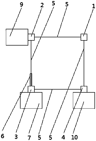
[0027] Step 1: Take the empty shaft. When the warp yarns on the warping machine 8 are about to be full, the control system starts the electromagnetic navigation system and the driving system, and the warping machine warp beam transfer robot 7 is driven by the driving system and carried out by the electromagnetic navigation system. Navigate from the standby charging position 1 to the empty shaft taking position 2, take out the empty shaft in the empty shaft storehouse 9 and place the empty shaft on the empty shaft temporary storage position on the warping machine warp beam transfer robot 7.

[0028]Step 2: Send the empty shaft. After the warp beam transfer robot 7 loads the empty shaft, the control system starts the electromagnetic navigation system and the drive system again, and the warp beam transfer robot 7 is driven by the drive system and driven ...

Embodiment 4

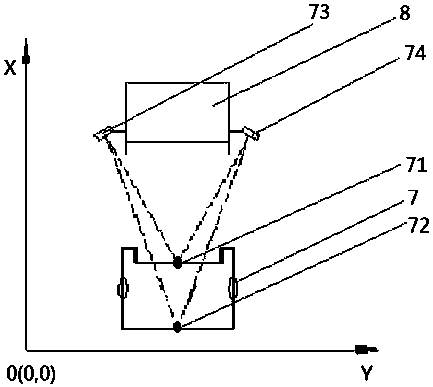
[0033] Embodiment 4, a control method of a warping beam transfer robot, the first laser emitter 71 is arranged at the front end of the warping beam transfer robot 7 and the coordinates are A(x 1 ,y 1 ), the second laser emitter 72 is arranged on the rear end of the beam transfer robot 7 of the warping machine and the coordinates are B(x 2 ,y 2 ), the front and back of coordinate A and coordinate B correspond and the height of coordinate A is lower than the height of coordinate B, and a reflecting plate 73 is arranged on the left side of warping machine 8 and coordinate is R 1 (x a ,y a ), another reflecting plate 74 is arranged on the right side of the warping machine 8 and the coordinates are R 2 (x b ,y a ). When the laser receiver receives the laser signals of the first laser transmitter 71 and the second laser transmitter 72 respectively, the distance l between the two laser transmitters and the two laser receivers can be obtained sequentially through the laser rang...


PUM


Abstract

The invention discloses a warping machine warp beam transfer robot and a control method thereof. The problems that in the prior art, for the warping machine warp beam replacement process, the efficiency is low, the labor intensity of workers is large and potential safety hazards exist are solved. The working point positions of the warping machine warp beam transfer robot comprise a standby charging position, a hollow shaft taking position, a warping machine front butt joint position and a full shaft storage position; an electromagnetic navigation system and a laser positioning system are usedfor guiding the warping machine warp beam transfer robot to move between all the working point positions, and the movement sequence of the warping machine warp beam transfer robot comprises five stepsof hollow shaft taking, hollow shaft sending, full shaft replacing, full shaft storage and standby charging. The warping machine warp beam transfer robot has the advantages that the movement steps are simple, the operation sequence is reasonable, the automatic operation is realized, and the warp beam replacement efficiency is directly improved; and the control method is accurate and reliable, sothat rapid replacement and storage of the warping machine warp beam is realized.

Description

technical field [0001] The invention relates to the technical field of warp beam replacement, in particular to a warp beam transfer robot and a control method thereof. Background technique [0002] During the warping production process, the warp beams of the warping machine need to be cyclically replaced from the warping machine, so the warp beams need to be supported, moved and temporarily stored in the production workshop. At present, the existing device for transporting warp beams is a manual push-pull hydraulic trolley, which is suitable for the transportation of a single warp beam. The degree of automation is low, the labor intensity of workers is high, there are potential safety hazards, and the continuity of the process is low, and there is a possibility of mistransportation of warp beams. The situation seriously limits the production efficiency of warping. Contents of the invention [0003] In view of the deficiencies in the above-mentioned background technology, ...

Claims


Application Information

Patent Timeline
Patent Type & Authority Applications(China)
IPC IPC(8): B25J11/00B25J19/06B25J9/16
CPCB25J9/1676B25J11/00B25J19/061
Inventor 李铬张洪王庆华魏毅崔运喜刘汉申陈威望梁颖倪莉王好强
Owner ZHONGYUAN ENGINEERING COLLEGE
Why Eureka
Try Eureka