Deep-sea anchor-system subsurface-buoy system based on satellite communication data real-time transmission

A technology of satellite communication and real-time transmission, which is applied in the direction of buoys, transportation and packaging, special-purpose ships, etc., can solve the problems of easily damaged cable measuring instruments, increased difficulty, waste, etc., to avoid damage caused by equipment collision and entanglement, and run smoothly , the effect of a reasonable structure

Active Publication Date: 2018-06-22
THE FIRST INST OF OCEANOGRAPHY SOA
View PDF8 Cites 15 Cited by
  • Summary
  • Abstract
  • Description
  • Claims
  • Application Information

AI Technical Summary

Problems solved by technology

However, in the field of deep-sea marine monitoring, the instruments for detecting different water depths through submerged buoys are basically fixed, that is to say, ADCP and TD are generally set at a water depth of about 300-500 meters, and CTD and RCM are generally set at a water depth of about 800-1000 meters. In addition, an inductively coupled temperature-salt chain is installed about 50 to 100 meters below the water surface to monitor the profile measurement of seawater temperature, salinity, circulation, echo intensity and other marine environmental parameters at each depth. After the deployment is completed, data can only be collected for seawater information at a specific depth. At present, the total length of the submersible buoy is thousands of meters or even several kilometers, and once the deployment is completed, it cannot be adjusted arbitrarily.
Therefore, the acquired data is limited, and ocean data colle

Method used


Image

  • Deep-sea anchor-system subsurface-buoy system based on satellite communication data real-time transmission
  • Deep-sea anchor-system subsurface-buoy system based on satellite communication data real-time transmission
  • Deep-sea anchor-system subsurface-buoy system based on satellite communication data real-time transmission

Examples


Example Embodiment

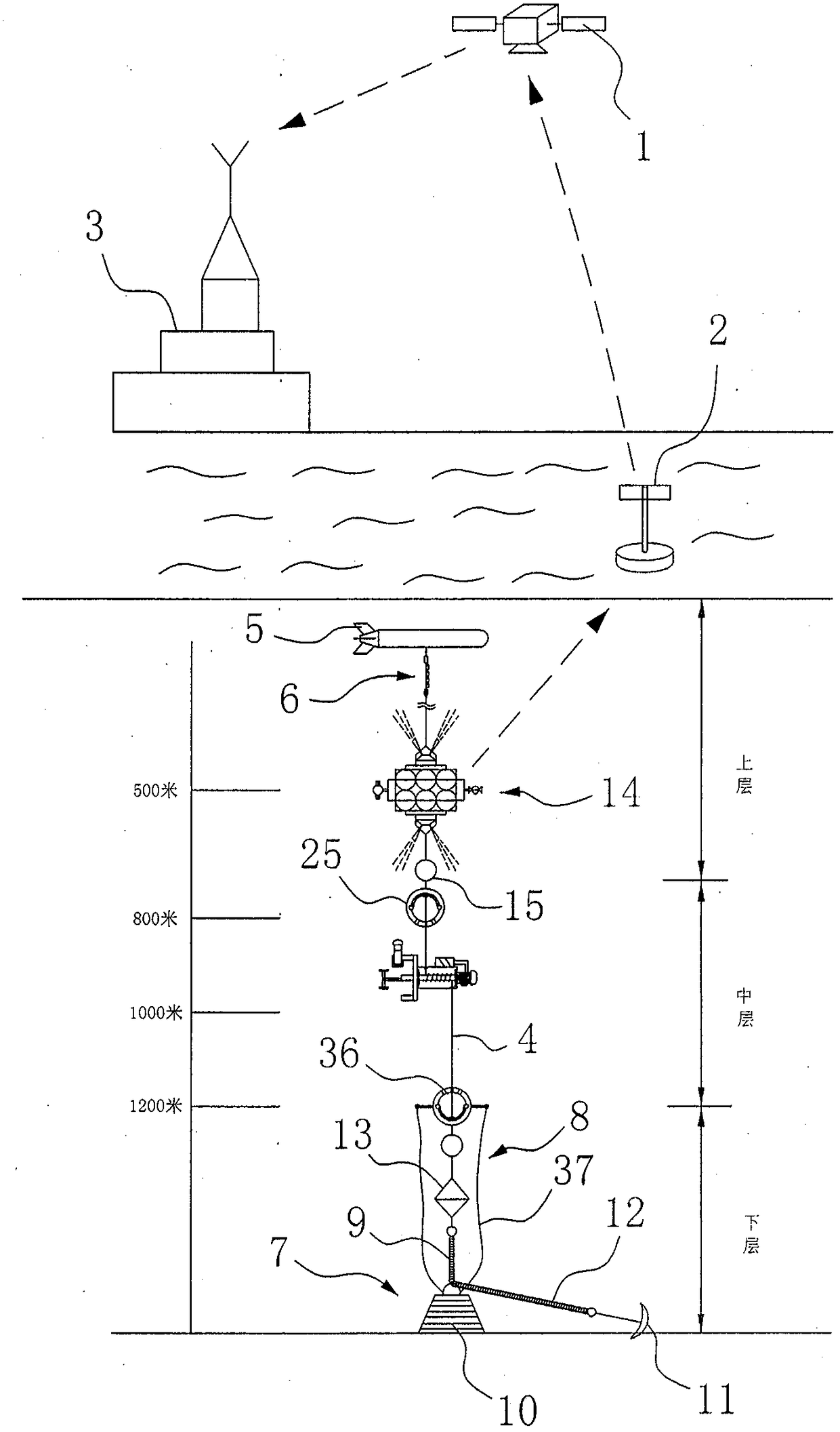
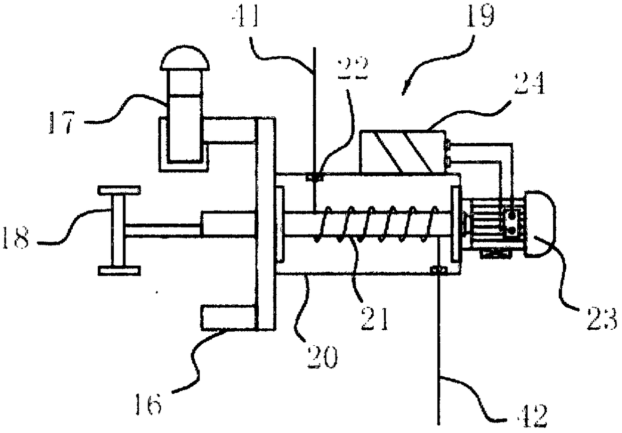
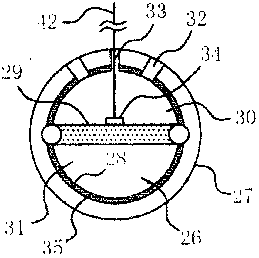
[0032] Below in conjunction with accompanying drawing and specific embodiment the present invention is described in further detail;

[0033] like figure 1 , 2 , 3, 4, 5, 6, 7, and 8, a deep-sea mooring submersible mark system based on real-time transmission of satellite communication data, including a profile measurement data for real-time reception of underwater collection and uploading the data to The surface buoy system 2 of the two-way communication satellite 1, the two-way communication satellite 1 feeds back the acquired real-time measurement data to the land laboratory 3; the surface buoy system 2 includes a surface buoy body, a satellite communication terminal, a mooring and communication cable, a satellite communication module, The buoy power supply, wherein the buoy power supply, satellite communication module, and satellite communication terminal are installed in the surface buoy body. It also includes a vertically arranged plastic-coated steel cable 4, and a sub-...


PUM


Abstract

The invention discloses a deep-sea anchor-system subsurface-buoy system based on satellite communication data real-time transmission. The deep-sea anchor-system subsurface-buoy system comprises a water-surface buoy system, a vertically-arranged plastic covered steel cable, a secondary floating body, an anchoring mooring part, a releasing unit, a primary floating body and a plurality of glass floating balls, and the deep-sea anchor-system subsurface-buoy system also comprises a frame body arranged between the main floating body and the releasing unit and used for carrying deepwater measuring apparatuses; a lifting adjusting mechanism for driving all the deepwater measuring apparatuses to move up and down along the plastic covered steel cable to measure measurement data of sections at different water-depth portions is arranged on the frame body. Through the lifting adjusting mechanism, continuous data monitoring of underwater preset depth distance sections can be achieved, and the void that continuous collection of section information under all temperature-salinit deepwater in different water depths cannot be carried out at present is filled; automatic control is achieved through a controller, the structure is reasonable, and running is stable; through an arranged lifting-adjusting auxiliary part, the resistance of the frame body in the ascending or descending process along the plastic covered steel cable is smaller, and running is more stable.

Description

technical field [0001] The invention relates to the technical field of ocean observation equipment, in particular to a deep sea mooring submersible buoy system based on real-time transmission of satellite communication data. Background technique [0002] Submersible buoy technology was used and developed by some marine developed countries in the 1960s; a system for long-term observation of marine environmental elements moored below the sea surface, and an acoustic release device can be recovered from the sea surface according to instructions. The buoy and submersible buoy system is an important technical equipment for marine environmental investigation. It has the characteristics of unattended long-term, continuous, synchronous and automatic comprehensive monitoring of various elements of marine hydrology and meteorology under harsh marine environmental conditions. The spatial and temporal expansion of marine observation shore stations, survey ships and survey aircraft is an...

Claims


Application Information

Patent Timeline
IPC IPC(8): B63B22/00B63B22/04B63B22/18G01D21/02
CPCB63B22/00B63B22/04B63B22/18B63B2022/006G01D21/02
Inventor 张浩然张志平李杨
Owner THE FIRST INST OF OCEANOGRAPHY SOA
Why Eureka
Try Eureka