Intelligent module

A technology of intelligent modules and wires, applied in the directions of registration/indication of machine work, registration/instruction, time register, etc., can solve the problem of increasing the work intensity of maintenance personnel, the inability to monitor the working time of elevators, and the inability to ensure the reliable use of elevators. problems such as stability, to achieve the effect of easy installation, reduced size, and avoidance of damage

Active Publication Date: 2018-06-22
CHENGDU ZHUOXIN IND
View PDF7 Cites 0 Cited by
  • Summary
  • Abstract
  • Description
  • Claims
  • Application Information

AI Technical Summary

Problems solved by technology

[0008] The anti-loosening elevator disclosed in this patent document, its anti-loosening device can be flexibly opened and closed, which is convenient for loading and unloading of the lifting ring, and has a certain anti-loosening effect. However, the working time of the elevator cannot be monitored, and the elevator needs to be inspected and maintained regularly , which increases the work intensity of the maintenance personnel, and cannot guarantee the reliability of the elevator

Method used


Image

  • Intelligent module
  • Intelligent module

Examples


Embodiment 1

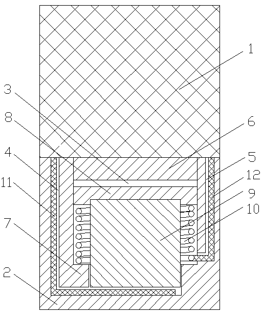
[0033] An intelligent module includes a chip 1 and a bracket 2, the chip 1 is fixed on the bracket 2, and the inside of the bracket 2 is provided with a mounting hole 3, a first wire channel 4 and a second wire channel 5, and the mounting hole 3 is provided with a plug 6 for closing the installation hole 3, and a step 7 is provided below the installation hole 3, and a limiter 8 and a magnet 9 are installed in the installation hole 3; the limiter 8 is a ferromagnetic metal, and the limiter The plate 8 is provided with a counterbore matching the diameter of the magnet 9, and the magnet 9 is inserted into the counterbore and absorbed into the limit piece 8 as a whole; the magnet 9 is cylindrical, and the outside of the magnet 9 is covered with a spring 10. One end of the spring 10 is in contact with the step 7, and the other end is in contact with the stopper 8; the first wire channel 4 is provided with a first wire 11, and the second wire channel 5 is provided with a second wire 12...

Embodiment 2

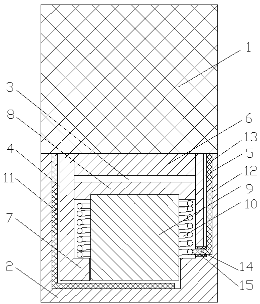
[0036] An intelligent module includes a chip 1 and a bracket 2, the chip 1 is fixed on the bracket 2, and the inside of the bracket 2 is provided with a mounting hole 3, a first wire channel 4 and a second wire channel 5, and the mounting hole 3 is provided with a plug 6 for closing the installation hole 3, and a step 7 is provided below the installation hole 3, and a limiter 8 and a magnet 9 are installed in the installation hole 3; the limiter 8 is a ferromagnetic metal, and the limiter The plate 8 is provided with a counterbore matching the diameter of the magnet 9, and the magnet 9 is inserted into the counterbore and absorbed into the limit piece 8 as a whole; the magnet 9 is cylindrical, and the outside of the magnet 9 is covered with a spring 10. One end of the spring 10 is in contact with the step 7, and the other end is in contact with the stopper 8; the first wire channel 4 is provided with a first wire 11, and the second wire channel 5 is provided with a second wire ...

Embodiment 3

[0044] An intelligent module includes a chip 1 and a bracket 2, the chip 1 is fixed on the bracket 2, and the inside of the bracket 2 is provided with a mounting hole 3, a first wire channel 4 and a second wire channel 5, and the mounting hole 3 is provided with a plug 6 for closing the installation hole 3, and a step 7 is provided below the installation hole 3, and a limiter 8 and a magnet 9 are installed in the installation hole 3; the limiter 8 is a ferromagnetic metal, and the limiter The plate 8 is provided with a counterbore matching the diameter of the magnet 9, and the magnet 9 is inserted into the counterbore and absorbed into the limit piece 8 as a whole; the magnet 9 is cylindrical, and the outside of the magnet 9 is covered with a spring 10. One end of the spring 10 is in contact with the step 7, and the other end is in contact with the stopper 8; the first wire channel 4 is provided with a first wire 11, and the second wire channel 5 is provided with a second wire ...


PUM


Abstract

The invention discloses an intelligent module, and belongs to the technical field of automatic control equipment. The intelligent module comprises a chip and is characterized by further comprising a bracket, the bracket is internally provided with a mounting hole, a first wire channel and a second wire channel, a plug is arranged above the mounting hole, a step is arranged below the mounting hole,and a limiting piece and a magnet are mounted in the mounting hole; the outer side of the magnet is sleeved with a spring, one end of the spring makes contact with the step, and the other end of thespring makes contact with the limiting piece; and the first wire channel is internally provided with a first wire, and the second wire channel is provided with a second wire, the first wire channel communicates with the mounting hole, one end of the first wire is connected with the chip, the other end of the first wire is located below the magnet, one end of the second wire is connected with the spring, and the other end of the second wire is connected with the chip. The intelligent module can automatically monitor and record the working time of the equipment, periodical manual recording is not required, using reliability and safety of the equipment can be ensured, and the working intensity of maintenance personnel can be reduced.

Description

technical field [0001] The invention relates to the technical field of automatic control equipment, in particular to an intelligent module suitable for oil drilling engineering equipment. Background technique [0002] In drilling engineering, an elevator is a tool used to lift pipes such as drill pipes, oil pipes and casings. It is hung in the lifting rings on both sides of the hook of the hoisting system, so as to lift out or run in the drilling tool, tubing and casing of the wellbore. [0003] Elevators are mainly divided into casing elevators, tubing elevators, drill pipe elevators and sucker rod elevators. [0004] Casing elevator is an essential tool for lifting and running casing in oil and gas drilling operations. The casing elevator is made of special alloy steel, which is light in weight, small in size and large in load, which greatly reduces the working intensity of users. Casing elevator is mainly composed of main body, valve, lock pin assembly, special handle ...

Claims


Application Information

Patent Timeline
Patent Type & Authority Applications(China)
IPC IPC(8): E21B19/06G07C3/02
Inventor 池振华邹益文卢伟
Owner CHENGDU ZHUOXIN IND
Why Eureka
Try Eureka