Penetration grouting test system and method for reinforced loose gravelly soil
A grouting test and gravel soil technology, applied in the field of rock engineering, can solve the problems of limited application, limited system exploration and research, and inability to directly observe the law of grouting fluid penetration and diffusion, and achieve precise control and high strength of tempered glass. Effect
- Summary
- Abstract
- Description
- Claims
- Application Information
AI Technical Summary
Problems solved by technology
Method used
Image
Examples
Embodiment 1
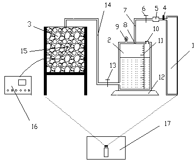
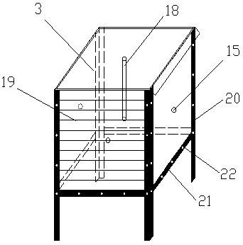
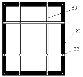
[0047] Example 1: Such as Figure 1~6 As shown, a penetration grouting test system for strengthening loose gravel soil includes a grouting pressure supply device 1, a grouting fluid storage device 2, a grouting test box 3, a grouting parameter monitoring device, and a grouting pressure supply device 1 The outlet end of the grouting fluid storage device 2 is connected to the vent 8 at the top center of the grouting fluid storage device 2 through the pressure pipe 7, and the grouting hole at the bottom of the grouting fluid storage device 2 passes through the liquid pipe 14 and the grouting pipe 18 of the grouting test box 3 Connected, the grouting pipe 18 is vertically fixed at the center of the top wall of the grouting test box 3 and extends downward into the grouting test box.
[0048] The grouting pressure supply device 1 includes a power device, a pressure regulating valve 4, and a pressure reducer 5. The pressure regulating valve 4 and a pressure reducer 5 are installed at th...
Embodiment 2
[0066] Example 2: The structure of the penetration grouting test system for strengthening loose gravel soil in this example is basically the same as the structure of the penetration grouting test system for strengthening loose gravel soil in Example 1, except that the power device is For the air compressor, the spacing between the scale lines 19 is 10 cm, the grouting pipe 18 is a cylindrical infiltration grouting pipe 27, and the space between the osmometer-temperature sensor pair is 10 cm.
Embodiment 3
[0067] Example 3: The structure of the penetration grouting test system for strengthening loose gravel soil in this example is basically the same as the structure of the penetration grouting test system for strengthening loose gravel soil in Example 1, except for the scale line 19 The distance between the grouting pipe 18 is a column-hemispherical infiltration grouting pipe 28, and the space between the osmometer-temperature sensor pair is 15 cm.
PUM
| Property | Measurement | Unit |
|---|---|---|
| Diameter | aaaaa | aaaaa |
| Height | aaaaa | aaaaa |
| Side length | aaaaa | aaaaa |
Abstract
Description
Claims
Application Information
 - R&D
- Intellectual Property
- Life Sciences
- Materials
- Tech Scout
- Unparalleled Data Quality
- Higher Quality Content
- 60% Fewer Hallucinations
Browse by: Latest US Patents, China's latest patents, Technical Efficacy Thesaurus, Application Domain, Technology Topic, Popular Technical Reports.
© 2025 PatSnap. All rights reserved.Legal|Privacy policy|Modern Slavery Act Transparency Statement|Sitemap|About US| Contact US: help@patsnap.com


