
POS (point of sale) Terminal

A terminal and display technology, applied in electromagnetic radiation induction, instruments, induction record carriers, etc., can solve the problems of non-compliance, fatigue, slow scanning speed, etc., achieve reasonable weight, improve scanning efficiency, and cost controllable Effect

Pending Publication Date: 2018-06-22
黎煜电子科技(上海)有限公司
View PDF9 Cites 0 Cited by
  • Summary
  • Abstract
  • Description
  • Claims
  • Application Information

AI Technical Summary

Problems solved by technology

In the case where the scanning code collector is designed on the back, merchant users need to hold the terminal when scanning the QR code, keep looking at the screen, and move the terminal so that the scanned QR code enters the range bounded by the scanning frame displayed on the screen In order to scan the code effectively, it takes time for the camera to focus. Although various technical improvements have been adopted, in terms of effect, the scanning speed is slow, which leads to a long waiting time for consumers to pay.
Especially for merchants with a large passenger flow, it causes consumers to queue up to pay, which is inefficient
When the code scanning collector is designed on the front, it does not conform to the habit of consumers to hold the mobile phone vertically to scan codes for the POS terminal. The patent application of Fujian Liandi Commercial Equipment Co., Ltd. (application number CN201610123200.5 ) is an improvement to this situation, but this improvement is not realistically practicable due to its incongruous appearance
On the other hand, because the existing design is a continuous function expansion, the scan code payment scenario is not considered enough, resulting in the existing scan code operation not conforming to human mechanics, and merchant users are prone to fatigue due to operations such as holding hands for a long time and staring at the screen, and the user experience is poor. Difference

Method used


Image

  • POS (point of sale) Terminal
  • POS (point of sale) Terminal
  • POS (point of sale) Terminal

Examples


Embodiment Construction

[0017] The specific implementation of the POS terminal provided by the present invention will be described in detail below in conjunction with the accompanying drawings.

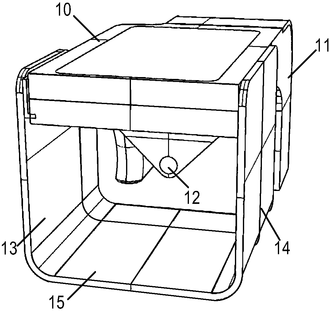
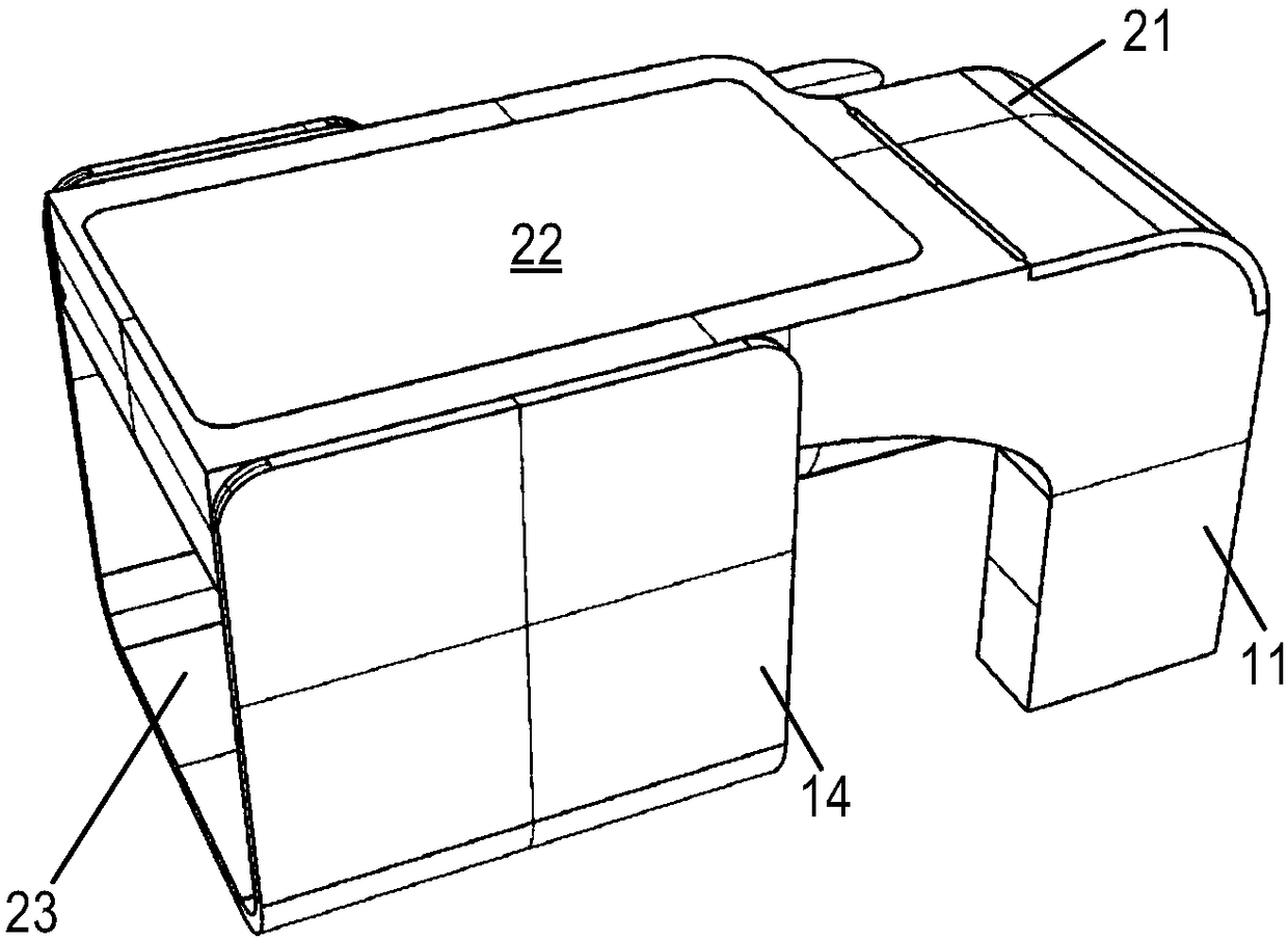
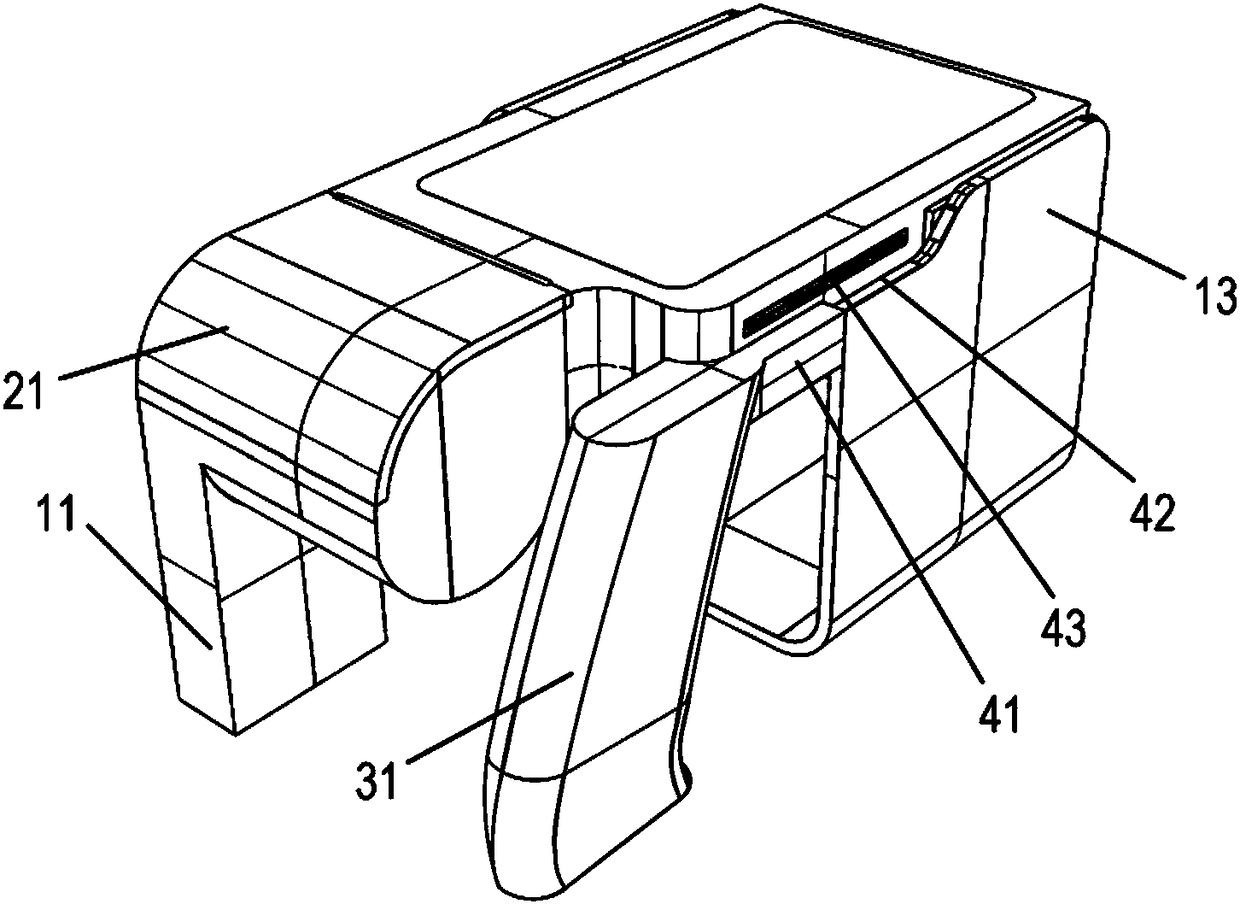
[0018] This specific embodiment provides a POS terminal, with figure 1 It is a schematic diagram of the first angle of the POS terminal in the specific embodiment of the present invention, with figure 2 It is a schematic diagram of the second angle of the POS terminal in the specific embodiment of the present invention, with image 3 It is a schematic diagram of the third angle of the POS terminal in the specific embodiment of the present invention, with Figure 4 It is a schematic diagram of the fourth angle of the POS terminal in the specific embodiment of the present invention; Figure 5 It is a schematic diagram of the fifth angle of the POS terminal in the specific implementation manner of the present invention.

[0019] Such as Figure 1-5 As shown, the POS terminal provided in this specific embod...


PUM


Abstract

The invention relates to the technical field of point-of-sale terminal, in particular to a novel POC (point of sale) terminal, comprising a display screen that can display a UI (user interface) of a commercial user; the UI defines a top-down direction of the display screen via the top-down direction of a picture and / or text displayed; the display screen is positioned on the upper surface of the POS terminal to provide a user view of the commercial user; front-back position of the POS terminal is defined via the top-down position of the display screen; the POS terminal also comprises a card handling device, a printer, a code-scanning acquisition chamber, a code-scanning acquirer and a handheld portion. To conform to the trend of increasingly frequent usage of code-scanning payment, the handheld feature and a scanning window feature are added to the design of POS terminal; the POS terminal meets the human mechanics, is suitable for merchants to use for long time to fight against fatigue,and enables code scanning to be quickly completed and code-scanning payment efficiency to be improved.

Description

technical field [0001] The invention relates to the technical field of point-of-sale terminals, in particular to a novel POS terminal. Background technique [0002] POS (Point of sales) terminal is a terminal reader equipped with readable codes such as barcodes or OCR (Optical Character Recognition) codes, and has functions such as cash transactions or barter quota cashiers. The POS terminal is connected to the settlement system of the trading platform, and its main function is to provide data services and management for commodity transactions, and to perform non-cash settlement. In order to expand the function of the POS terminal, a printer is installed in the existing POS terminal, which is used to print the customer's shopping details, payment proof after swiping the card, and the like. [0003] With the development of global bank card payment and mobile payment, especially the further popularization of code scanning payment methods such as WeChat payment and Alipay, the...

Claims


Application Information

Patent Timeline
Patent Type & Authority Applications(China)
IPC IPC(8): G07G1/00G06K7/10
CPCG06K7/10861G07G1/0018G07G1/0081
Inventor 陈黎煜
Owner 黎煜电子科技(上海)有限公司
Learn More