Microwave heating treatment system for high-radioactivity nuclear industry waste
A microwave heating and high radioactivity technology, which is applied in the field of microwave heating treatment system of high radioactive nuclear industrial waste, can solve the problems of increasing nuclear radiation risk, affecting process efficiency, pipeline blockage, etc., and achieves good radiation protection effect, simple motion relationship, and improved The effect of service life
- Summary
- Abstract
- Description
- Claims
- Application Information
AI Technical Summary
Problems solved by technology
Method used
Image
Examples
Embodiment 1
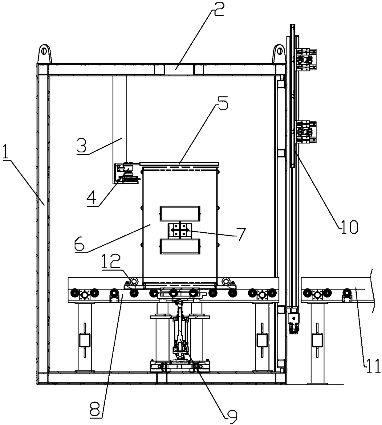
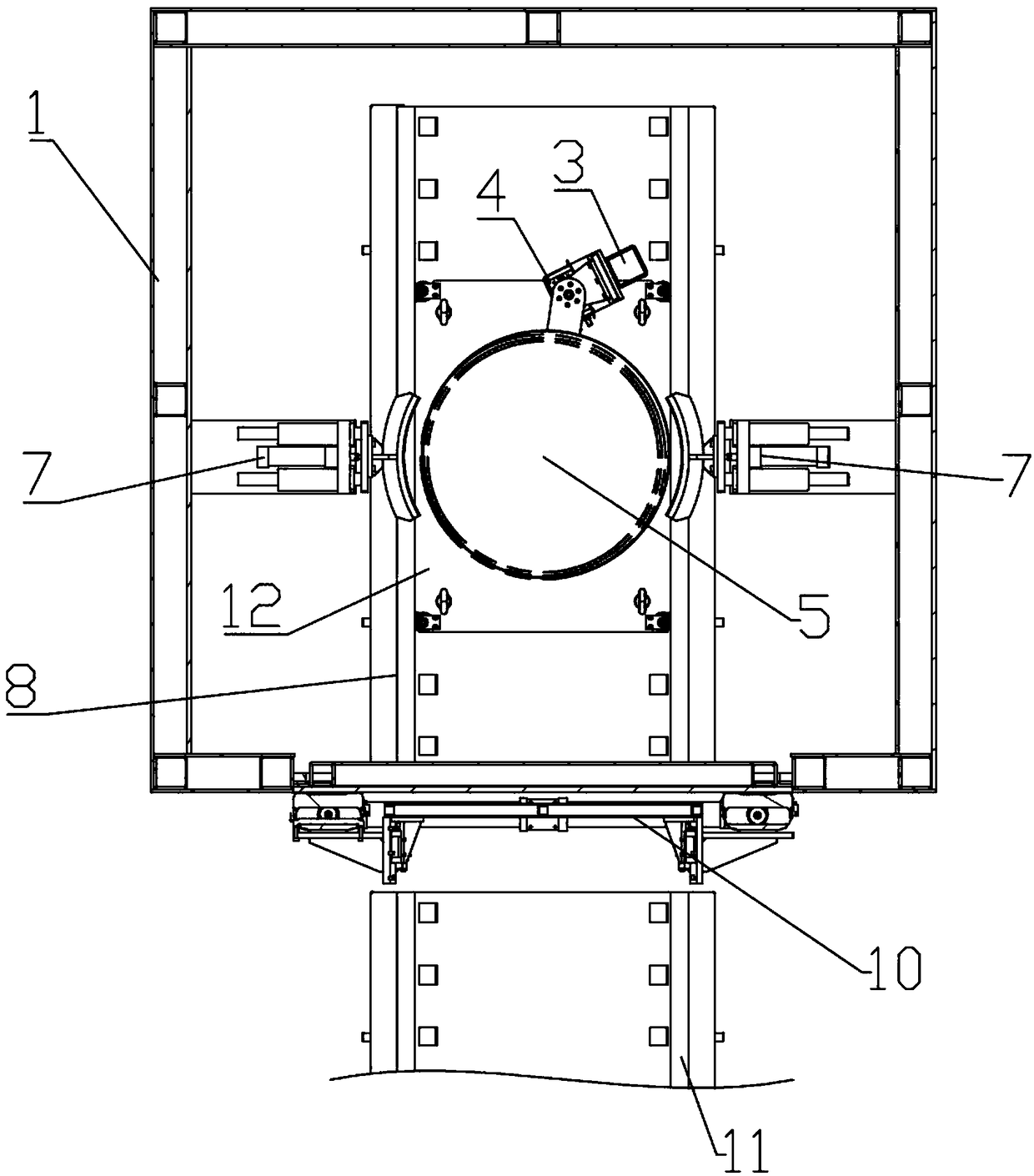
[0051] A microwave heating treatment system for high radioactive nuclear industrial waste, its structure is as follows Figure 1 to Figure 3 As shown, it includes a sealed box 1 and a control system. The top of the sealed box 1 is provided with a microwave heating hole 2 and an exhaust hole for discharging water vapor. A lifting device 9 is arranged below the microwave heating hole 2. A sealed door 10 is provided, and the inside of the sealed box 1 is provided with a transmission device I8 for sending the barrel 6 containing high-level waste liquid to or from the lifting device 9, and the outside of the sealed box 1 is equipped with a transmission device II11, and a transmission device I8 The height matches with the transmission device II11 and is located on both sides of the airtight door 10 respectively. The control system includes a touch screen and a PLC controller electrically connected to the touch screen. The PLC controller is connected to the transmission device I, the ...
Embodiment 2
[0054] On the basis of Embodiment 1, the transmission device I8 and the transmission device II11 are roller conveyors, the PLC controller is electrically connected to a frequency converter, and the frequency converter is connected to the motors of the transmission device I and the transmission device II respectively, and the motor is connected with a set A pair of limit switches are respectively provided on the gear set, the transmission device I8 and the transmission device II11, and the transmission device I8 is provided with a tray 12 for carrying the bucket 6 containing the high-level waste liquid and moving between the transmission device I8 and the transmission device II11 , the tray 12 has a structure such as Figure 5 As shown, it includes a tray main body 1201. On both sides of the tray main body 1201, there are at least a pair of rotating assemblies 1202 that can roll relative to the side walls of the conveyor I8 and conveyor II11. The upper surface of the tray body 1...
Embodiment 3
[0058] On the basis of Embodiment 1, the structure of the airtight door 10 is as follows: Figure 7 with Figure 8 As shown, it includes a large door panel 1006 and a small door panel 1002. The edge of the large door panel 1006 is provided with a plurality of screw holes, and the screw holes are used to fix the large door panel on the door frame 10010. The door frame 10010 is fixedly installed on the box body 1 that needs to be sealed. A sealing strip is provided between the sealed box body 1 to enhance the sealing performance, and a linear sliding mechanism I1005 parallel to the length direction of the door panel 1006 is provided on the sides of the door panel 1006, and the chute of the linear sliding mechanism I1005 passes through the screw Be fixed on the door plate 1006.
[0059] A plurality of pressing mechanisms 1001 for pressing the small door panel 1002 on the large door panel 1006 are fixedly connected to the slider of the linear sliding mechanism I1005 by screws. Th...
PUM
 Abstract
Description
Claims
Application Information
 - R&D
- Intellectual Property
- Life Sciences
- Materials
- Tech Scout
- Unparalleled Data Quality
- Higher Quality Content
- 60% Fewer Hallucinations
Browse by: Latest US Patents, China's latest patents, Technical Efficacy Thesaurus, Application Domain, Technology Topic, Popular Technical Reports.
© 2025 PatSnap. All rights reserved.Legal|Privacy policy|Modern Slavery Act Transparency Statement|Sitemap|About US| Contact US: help@patsnap.com


