Driving pressurized extrusion friction composite lead damper.

A composite lead and damper technology, applied in protective buildings/shelters, building components, building structures, etc., can solve problems such as difficult processing, lead leakage, and small stress area, and achieve high work efficiency, The effect of low lead consumption and convenient processing

Pending Publication Date: 2018-06-26
SHANGHAI KUNYI SEISMIC DAMPING ENG TECH CO LTD
View PDF5 Cites 0 Cited by
  • Summary
  • Abstract
  • Description
  • Claims
  • Application Information

AI Technical Summary

Problems solved by technology

However, the lead extrusion damper can only dissipate energy by extruding the lead and rubbing the lead through the convex part on the extrusion shaft. The stress area between the convex part and the lead is small and the efficiency is low.
In addition, since the sealing layer between the outer sleeve and the extrusion shaft is located in the movement direction of the motion shaft, the sealing layer has a large force surface, and if it is not tightly combined with the outer sleeve and the extrusion shaft, lead leakage will easily occur
At the same time, due to the special shape of the extrusion shaft, it needs to be melted and filled with lead and manufactured by a milling machine, which is difficult to process and expensive

Method used


Image

  • Driving pressurized extrusion friction composite lead damper.
  • Driving pressurized extrusion friction composite lead damper.
  • Driving pressurized extrusion friction composite lead damper.

Examples


Embodiment Construction

[0049] The present invention will be further described below in conjunction with the accompanying drawings and specific embodiments.

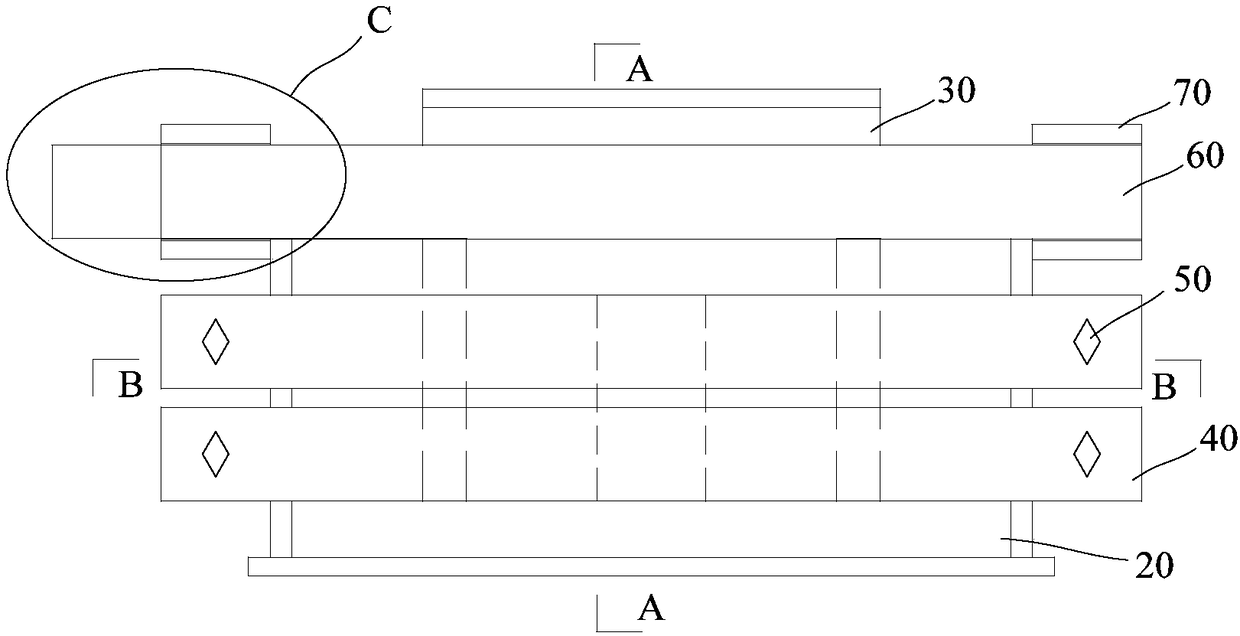
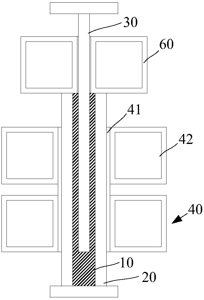
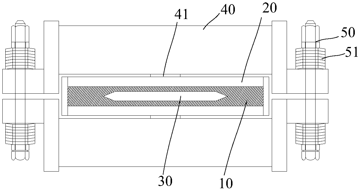
[0050] refer to figure 1 , shows a schematic diagram of the first embodiment of the active pressurized squeeze-friction composite lead damper of the present invention. refer to figure 2 ,shown figure 1 Sectional view of A-A in Fig. refer to image 3 ,shown figure 1 Sectional view of B-B in middle. refer to Figure 4 ,shown figure 1 Side view of C. combine Figure 1 to Figure 4As shown, the active pressurized extrusion friction composite lead damper of the present invention comprises: a lead storage box 20 with lead 10 inside, and an opening communicating with the inside is provided on the lead storage box 20; The insert plate 30 in the box 20, the insert plate 30 is partly exposed outside the lead storage box 20, and the insert plate 30 can move in the lead storage box 20; structure, the extrusion structure exerts a clamping force o...


PUM


Abstract

The invention relates to a driving pressurized extrusion friction composite lead damper. The driving pressurized extrusion friction composite lead damper comprises a lead storage box, an inserting plate and extrusion structures, wherein lead is contained in the lead storage box, and an opening in communication with the inner portion of the lead storage box is formed in the lead storage box; the inserting plate is inserted into the lead storage box in a sealing mode by the opening, part of the inserting plate exposes outside the lead storage box, and the inserting plate can move in the lead storage box; and the extrusion structures are arranged on the opposite sides of the lead storage box, the extrusion structures exert clamping force on the side portion corresponding to the lead storage box, when the damper is stressed, the inserting plate moves in the lead storage box and produces extrusion and friction energy consumption with the lead in the lead storage box at the end portion of the inserting plate and the loading range of the extrusion structures. According to the driving pressurized extrusion friction composite lead damper, extrusion and friction area between the lead and steel is large, materials are saved, and the efficiency is high. The inserting plate and the lead storage box are simple in structure, so that the damper can adopt a lead plate and a steel plate to carryout cold-working assembly, and the process is convenient and lead-free. The sealing direction of a sealing layer is perpendicular to the movement direction of a moving part, and the width of a sealing surface on the extrusion area with large force is very narrow, so that the sealing difficulty is low and the sealing performance is good.

Description

technical field [0001] The invention relates to the anti-seismic field of building construction, in particular to an active pressurized extrusion friction composite lead damper. Background technique [0002] Article number: 1671-4512 (2006) 06-0115-03 The research on lead squeeze damper is disclosed: the basic forms of energy dissipation devices are all kinds of dampers, lead dampers belong to metal yield dampers, and their damping materials are metal Lead, the crystalline structure of lead is a face-core cube, with many slip systems and slip directions, good plastic deformation ability, high flexibility and ductility, and dynamic recovery and dynamic recrystallization will occur at the same time when deformed at room temperature Through the process of recovery and recrystallization, the strain hardening disappears, and the structure and performance of lead will return to the state before deformation, so there will be no residual stress and no fatigue. Therefore, the perfor...

Claims


Application Information

Patent Timeline
Patent Type & Authority Applications(China)
IPC IPC(8): E04H9/02E04B1/98
CPCE04H9/02E04H9/0235E04H9/0215
Inventor 戴轶苏邓文艳彪仿俊张煜赵忻
Owner SHANGHAI KUNYI SEISMIC DAMPING ENG TECH CO LTD
Why Eureka
Try Eureka