New energy vehicle battery pack heat-dissipating device

A new energy vehicle and cooling device technology, applied to battery pack parts, batteries, secondary batteries, etc., can solve the problems of high cost, poor heat dissipation performance, etc., to improve service life, high heat dissipation efficiency, and speed up air circulation Effect

Inactive Publication Date: 2018-06-26
中山市榄商置业发展有限公司
View PDF8 Cites 9 Cited by
  • Summary
  • Abstract
  • Description
  • Claims
  • Application Information

AI Technical Summary

Problems solved by technology

[0003] The purpose of the present invention is to provide a heat sink for a new energy vehicle battery pack to solve the problem of poor heat dissipation and high cost of the exist

Method used


Image

  • New energy vehicle battery pack heat-dissipating device
  • New energy vehicle battery pack heat-dissipating device

Examples


Embodiment 1

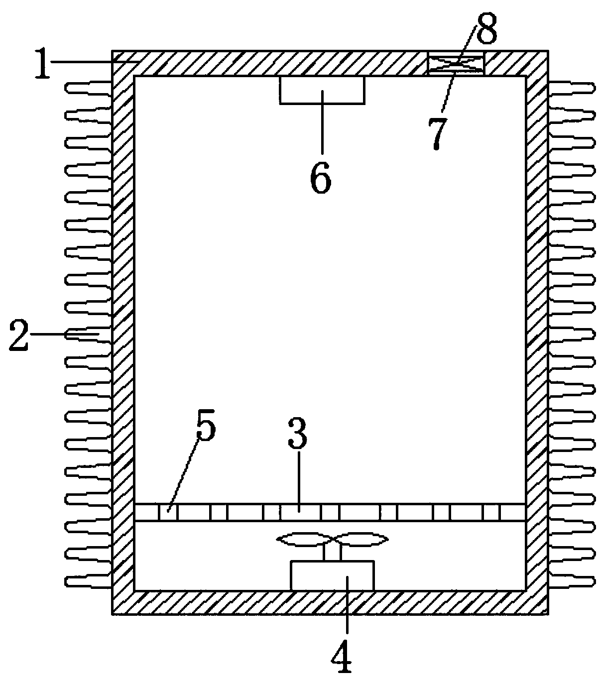
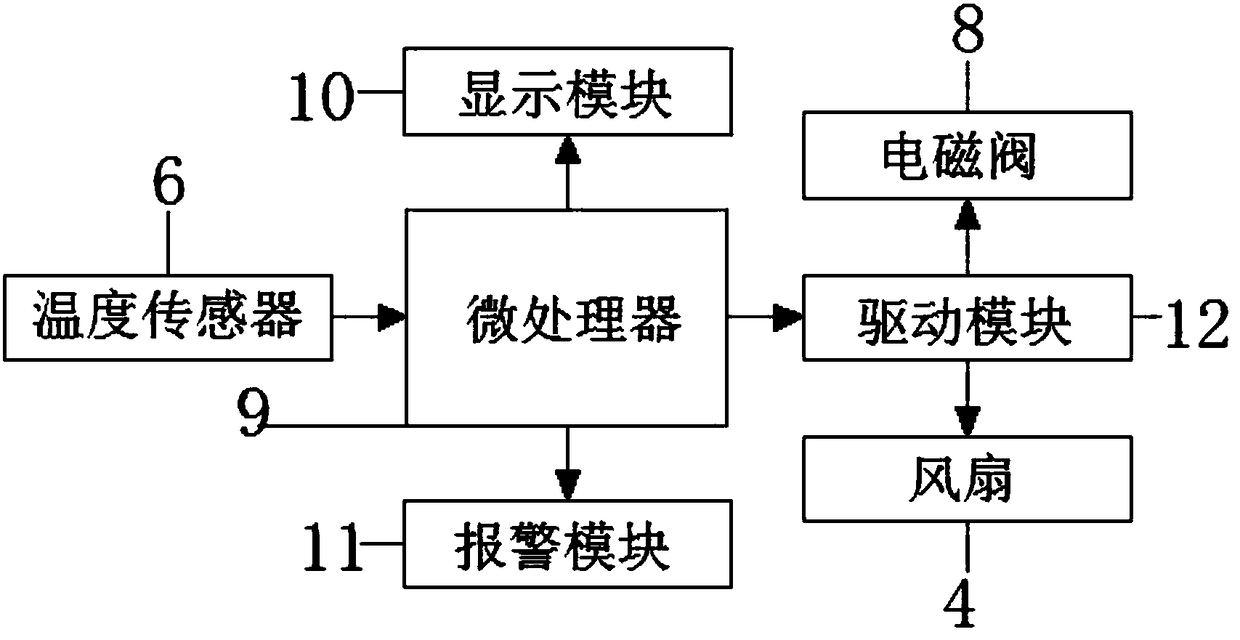
[0018] The new energy vehicle battery pack cooling device includes a box body 1, the left and right sides of the box body 1 are evenly provided with cooling fins 2, the bottom of the inner cavity of the box body 1 is provided with a fan 4 and a partition 3, and the partition The plate 3 is located above the fan 4, the partition 3 is evenly opened with through holes 5, the top of the inner cavity of the box body 1 is provided with a temperature sensor 6, and the top right side of the box body 1 is opened with a vent 7 , the cavity of the vent 7 is provided with a solenoid valve 8, the output end of the temperature sensor 6 is electrically connected to the input end of the microprocessor 9, and the output end of the microprocessor 9 is electrically connected to the display module 10 respectively , the input terminals of the alarm module 11 and the driving module 12, the output terminals of the driving module 12 are electrically connected to the input terminals of the solenoid val...

Embodiment 2

[0022] In this embodiment, the diameter of the semicircular chamfer is 2.5 centimeters, the diameter of the semicircular transition part is 4 centimeters, the porosity of porous aluminum silicon carbide is 30%, aluminum, copper, manganese and titanium, the aluminum, copper , manganese and titanium are as follows: 90 parts of aluminum; 9 parts of copper; 1 part of manganese and 11 parts of titanium, and the rest are the same as in Example 1.

Embodiment 3

[0024] In this embodiment, the diameter of the semicircular chamfer is 1 cm, the diameter of the semicircular transition part is 3 cm, the porosity of the porous aluminum silicon carbide is 20%, aluminum, copper, manganese and titanium, the aluminum, copper , manganese and titanium are as follows: 80 parts of aluminum; 12 parts of copper; 2 parts of manganese and 11 parts of titanium, and all the other are the same as in Example 1.


PUM

PropertyMeasurementUnit
Diameteraaaaaaaaaa
Diameteraaaaaaaaaa
Porosityaaaaaaaaaa

Abstract

The present invention discloses a new energy vehicle battery pack heat-dissipating device, pertaining to the technical field of new energy. The device comprises a box body. The left side and the rightside of the box body are uniformly provided with heat-dissipating fins. The bottom of the inner cavity of the box body is provided with a fan and a partition plate, and the partition plate is locatedabove the fan. The partition plate is uniformly provided with through holes. The output terminal of a temperature sensor is electrically connected with the input terminal of a microprocessor, the output terminal of the microprocessor is electrically connected with the input terminals of a display module, an alarm module and a driving module separately, and the output terminal of the driving module is electrically connected with the input terminals of a solenoid valve and the fan separately. The device has the advantage of high heat dissipation efficiency. The arrangement of the heat-dissipating fins can accelerate air circulation and realize fast cooling. The heat-dissipating fins and the box body are made by adopting high conductivity material, so that the heat conduction efficiency is improved. When the temperature of a battery pack is too high, the device can perform further heat dissipation by using the fan, so that the service life of the new energy vehicle battery pack is improved.

Description

technical field [0001] The invention relates to the technical field of new energy, in particular to a heat dissipation device for a battery pack of a new energy vehicle. Background technique [0002] The energy storage of new energy vehicles (oil-electric hybrid vehicles and pure electric vehicles) requires the use of high-performance power batteries. During use, the internal temperature of the battery will rise due to high-current charging and discharging, making the battery temperature exceed its normal temperature. Use temperature, and even cause battery rupture, leakage, fire and explosion, thereby affecting the reliability and safety of the battery. The heat dissipation performance of the existing battery pack heat sink is poor, and the cost is too high, and the temperature monitoring of the battery pack cannot be well realized. Therefore, we propose a new energy vehicle battery pack heat sink. Contents of the invention [0003] The purpose of the present invention i...

Claims


Application Information

Patent Timeline
IPC IPC(8): H01M10/613H01M10/625H01M10/635H01M10/653H01M10/6551H01M10/6563H01M2/10H01M50/204
CPCH01M10/613H01M10/625H01M10/635H01M10/653H01M10/6551H01M10/6563H01M2220/20H01M50/20Y02E60/10
Inventor 梁荣强
Owner 中山市榄商置业发展有限公司
Why Eureka
Try Eureka