
Painting device for valve body of valve

A technology for painting device and valve body, which is applied to devices for coating liquid on the surface, coating, cleaning by electrostatic method, etc., which can solve the problems of cleaning dead corners of air intermediates, unable to blow air, and unable to achieve intermediate cleaning. , to achieve the effect of enhancing the dust removal effect and improving the processing efficiency

Inactive Publication Date: 2018-06-29
CHONGQING QIANYAN MACHINERY CO LTD
View PDF11 Cites 1 Cited by
  • Summary
  • Abstract
  • Description
  • Claims
  • Application Information

AI Technical Summary

Problems solved by technology

The existing dust removal process usually uses the conveyor belt to transfer the valve body to the blowing area, and uses the airflow impact to remove dust. However, because the valve body structure is in the shape of an "I", the connection between the intermediate body and the flanges on both sides has clamps. Angle, so that the airflow cannot be blown to the angled part, and the intermediate body has a cylindrical three-dimensional structure, and the airflow cannot flow to the part of the intermediate body facing away from the blower port, resulting in a clean dead angle on the intermediate body, so it is impossible to realize the cleaning of the intermediate body Thorough and effective cleaning

Method used


Image

  • Painting device for valve body of valve
  • Painting device for valve body of valve
  • Painting device for valve body of valve

Examples


Embodiment Construction

[0022] The present invention will be described in further detail below by means of specific embodiments:

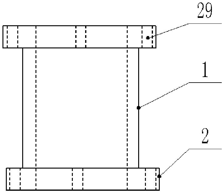
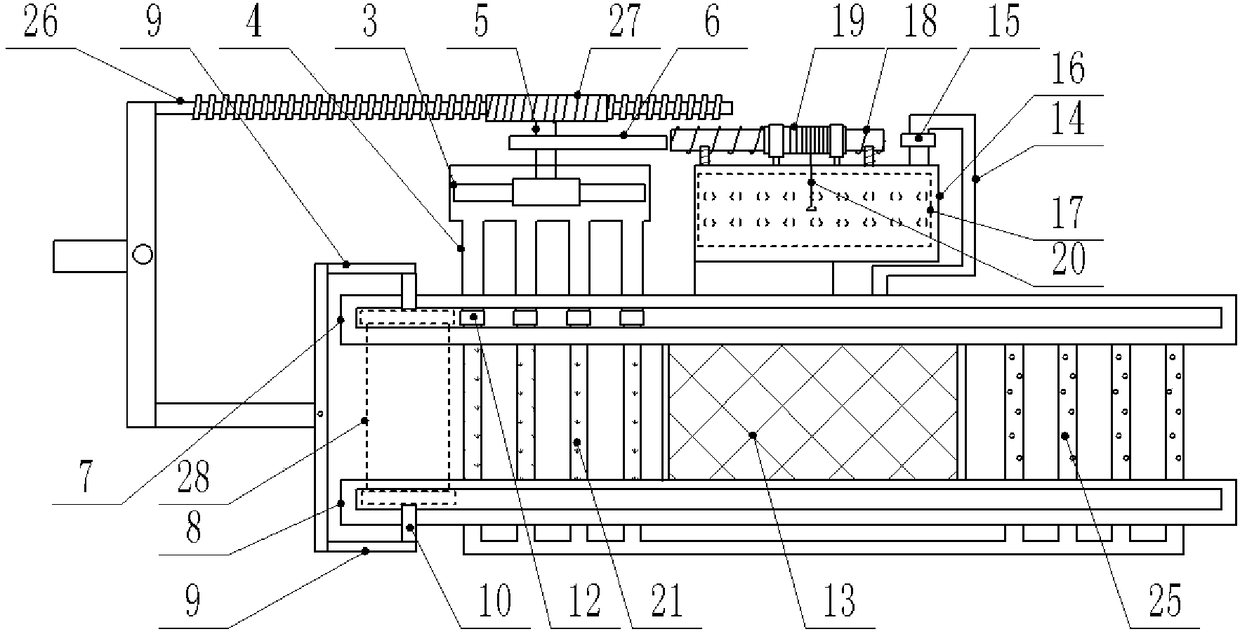
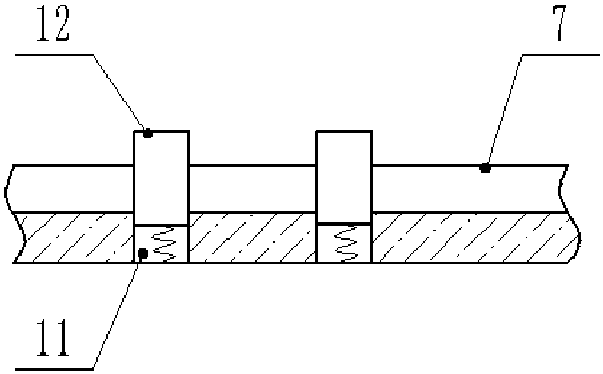
[0023] The reference signs in the drawings of the specification include: intermediate body 1, flange plate 2, fan 3, blowing pipe 4, rotating shaft 5, cam 6, first slide rail 7, second slide rail 8, slide arm 9, connector 10. Tank body 11, press block 12, paint tank 13, paint repair pipe 14, switch 15, paint repair box 16, slide plate 17, lead screw 18, lead screw pair 19, pull rope 20, dust removal pipe 21, through hole 22, bristle 23, elastic cord 24, paint-baking tube 25, worm screw 26, worm wheel 27, valve body 28, positioning hole 29.

[0024] Example figure 2 Shown: a painting device for a valve body, including a frame body, on which a first slide rail 7 and a second slide rail 8 parallel to each other are welded and fixed, and on the first slide rail 7 and the second slide rail 8 The sliding arm 9 is connected by sliding, and the connecting head 10 is connected ...


PUM


Abstract

The invention relates to the field of valve production, and discloses a painting device for a valve body of a valve. The painting device comprises a frame body; the frame body is provided with a firstslide rail and a second slide rail; the first slide rail is slidingly connected with a slide arm; the slide arm is rotationally connected with a connecting head; a painting groove and a dust removingmechanism are arranged between the first slide rail and the second slide rail; the dust removing mechanism comprises a fan and a dust removing pipe; the dust removing pipe is connected to the first slide rail and the second slide rail, and is provided with multiple through holes; multiple brush bristles are inserted in the through holes; the two ends of the brush bristles are respectively positioned in and outside the dust removing pipe; elastic ropes are connected between the parts, positioned in the through holes, of the brush bristles and the hole walls of the through holes; groove bodiesare formed in the first slide rail; pressing blocks are slidingly connected into the groove bodies, and are projected on the first slide rail; springs are connected between the lower ends of the pressing blocks and the bottoms of the groove bodies; the fan is connected with a wind blowing pipe; the wind blowing pipe is aligned to the dust removing pipe; and the wind blowing pipe and the dust removing pipe both butt against the pressing blocks. The painting device can comprehensively remove dust of the valve body to prevent influence on the painting quality by cleaning dead angles.

Description

technical field [0001] The invention relates to the field of valve production and processing, in particular to a painting device for a valve body. Background technique [0002] The valve is a control component in the fluid delivery system, which has functions such as cut-off, adjustment, flow diversion, reverse flow prevention, pressure stabilization, flow diversion or overflow pressure relief. The main structure of the valve includes a valve body, a valve core and a valve stem, wherein the valve body is generally as follows figure 1 The "I" shape shown, the main structure includes an intermediate body and a flange connected to both ends of the intermediate body. The flange is provided with a plurality of circular positioning holes that are evenly distributed in sequence. During the production and processing of the valve, in order to prevent the valve from being oxidized and rusted in a humid environment, the valve needs to be painted. The painted parts mainly include the i...

Claims


Application Information

Patent Timeline
Patent Type & Authority Applications(China)
IPC IPC(8): B05C1/06B05C9/10B05C9/12B05C11/10B08B6/00
CPCB05C1/06B05C9/10B05C9/12B05C11/1002B08B6/00
Inventor 罗贵良
Owner CHONGQING QIANYAN MACHINERY CO LTD
Learn More