Tooth direction slope compensation method in toothed-wheel grinding process

A compensation method and technology of tooth orientation, applied to components with teeth, gear tooth manufacturing devices, gear teeth, etc., can solve the problems of gears not being ground, large differences, and tooth surfaces not being polished, and improve grinding accuracy , the steps are simple, and the effect of improving the yield

Active Publication Date: 2018-06-29
CHONGQING MACHINE TOOL GROUP
View PDF6 Cites 0 Cited by
  • Summary
  • Abstract
  • Description
  • Claims
  • Application Information

AI Technical Summary

Problems solved by technology

However, due to the large difference between the actual helix angle and the theoretical helix angle of the tooth blank before grinding, some gears cannot be ground or the tooth surface cannot be ground.

Method used


Image

  • Tooth direction slope compensation method in toothed-wheel grinding process
  • Tooth direction slope compensation method in toothed-wheel grinding process

Examples


Embodiment Construction

[0017] The preferred embodiments of the present invention will be described in detail below with reference to the accompanying drawings.

[0018] As shown in the figure, the compensation method for the slope of the tooth direction during the gear grinding process in this embodiment includes the following steps:

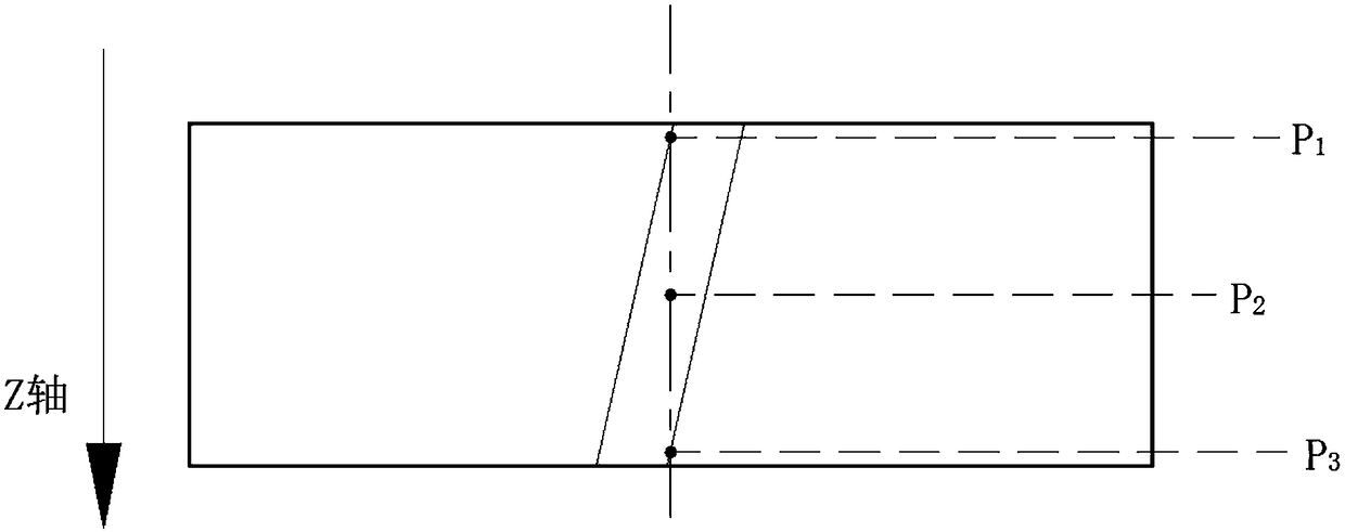
[0019] (1) After the first grinding (rough grinding) of the gear by the grinding wheel is completed, use the proximity switch set on the tool holder to read the center position P2 of a certain tooth groove on the current gear, and determine the corresponding position of P2 synchronously. P1 and P3 positions; said P1 and P3 are the corresponding intersection points of the vertical extension line passing through the P2 point on the current gear and the upper and lower groove lines of the tooth groove;

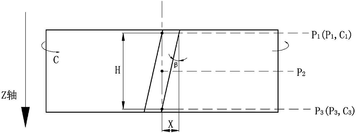
[0020] (2) Move the knife rest up and down along the gear width direction Z, and calculate the vertical distance H between the two points P1 and P3 through the program, ...


PUM


Abstract

The invention discloses a tooth direction slope compensation method in the toothed-wheel grinding process. According to the tooth direction slope compensation method, by means of a machine tool program, position coordinates of P1 and P3 on a toothed-wheel are confirmed, the actual helix angle of the toothed-wheel helix line is calculated through the coordinate values of the two points, the actualhelix angle is compared with the theoretical helix angle, thus the difference value of the actual helix angle and the theoretical helix angle is confirmed, the difference value is compensated into a system, the rectification of the helix angle is realized, so that grinding of all tooth surfaces is guaranteed. The tooth direction slope compensation method in the toothed-wheel grinding process is simple in overall steps and easy to control, the grinding precision of toothed-wheels can be greatly improved, and the finished product rate of products is improved.

Description

technical field [0001] The invention belongs to the field of gear grinding, and in particular relates to a method for compensating the slope of a tooth direction during a gear grinding process. Background technique [0002] In general, the worm grinding wheel grinding machine needs to carry out tooth alignment work before grinding the gear teeth, so as to ensure good meshing between the tooth grooves of the grinding wheel and the gear tooth body, so as to ensure the alignment between the grinding wheel and the tooth grooves of the gear during the grinding process sex. When processing paired teeth, a proximity switch is usually used to detect the P2 position in the middle of the gear (see figure 1 ), through the switch signal and the table rotation angle to judge whether the remaining margin on the gear is uniform, if the gear runout exceeds the set value, the workpiece will be rejected and not processed, if the runout value is within the set value range, then Grinding is p...

Claims


Application Information

Patent Timeline
Patent Type & Authority Applications(China)
IPC IPC(8): B23F23/00B23F19/00
CPCB23F19/00B23F23/00
Inventor 刘一冉余凯飞李轩张海亮
Owner CHONGQING MACHINE TOOL GROUP
Why Eureka
Try Eureka