Friction stir welding fixture and method for aluminum alloy frame
An aluminum alloy frame, friction stir technology, applied in welding equipment, welding equipment, auxiliary welding equipment, etc., can solve the problems of difficult clamping and positioning, small welding deformation, small residual stress, etc., and achieve accurate clamping positioning and welding deformation. The effect of small size and low processing cost
- Summary
- Abstract
- Description
- Claims
- Application Information
AI Technical Summary
Problems solved by technology
Method used
Image
Examples
Embodiment 1
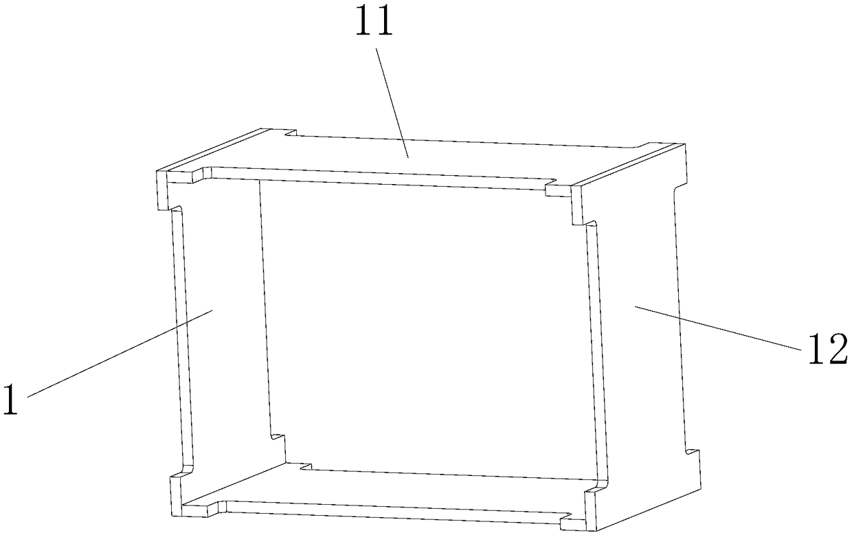
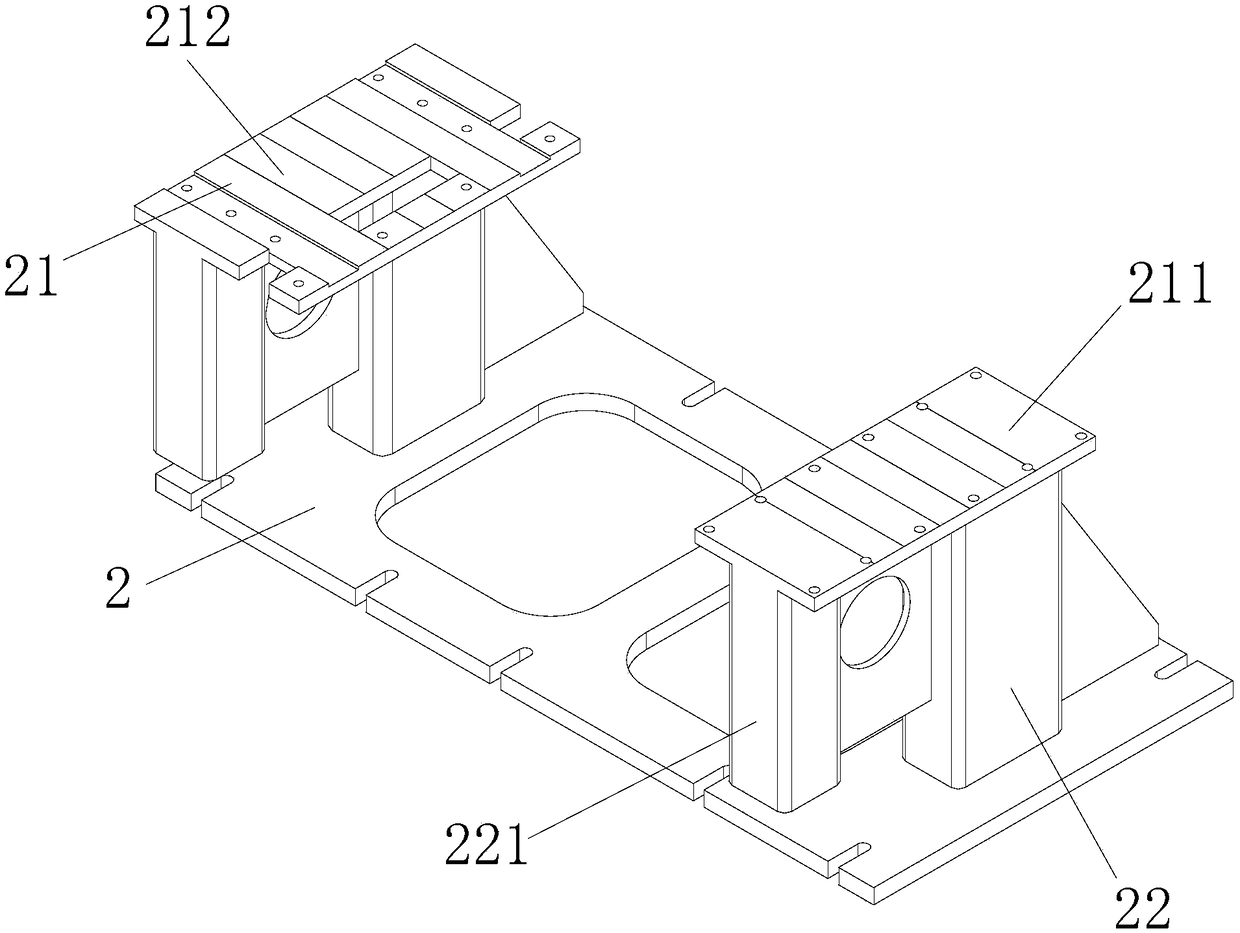
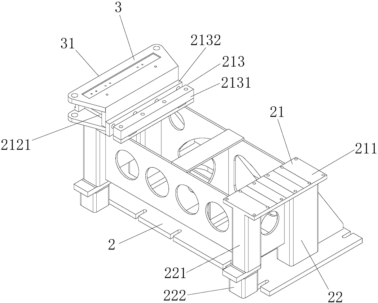
[0036] like Figure 1 to Figure 5As shown, the friction stir welding fixture of the aluminum alloy frame in this embodiment, the aluminum alloy frame 1 includes two horizontal plates 11 and two vertical plates 12, specifically, the horizontal plate 11 and the vertical plate 12 are industrial The font plate, the clamp includes a support frame 2 and two support boxes 3 for clamping and fixing the end of the horizontal plate 11 against the end side of the vertical plate 12, and the support frame 2 includes a support surface 21 and support legs 22 , the supporting legs 22 are detachable supporting legs 22 that can be partially or completely disassembled for the aluminum alloy frame body 1 to take out. The supporting boxes 3 are arranged on both sides of the supporting surface 21. The positioning mechanism 32 for positioning and locking, the pressing mechanism 33 for compressing the horizontal plate 11 in the vertical direction, the side positioning mechanism 34 for positioning and...
Embodiment 2
[0043] The friction stir welding jig of the aluminum alloy frame of this embodiment is basically the same as that of Embodiment 1, the main difference is that, as Image 6 and Figure 7 As shown, the support frame 2 of this embodiment further includes an adjustment guide rail 23 , and the support legs 22 are arranged on the adjustment guide rail 23 and can move along the adjustment guide rail 23 to adjust the distance between the support legs 22 . Specifically, the supporting leg 22 includes a front supporting leg and a rear supporting leg, wherein the rear supporting leg is arranged on the adjusting guide rail 23, and the front supporting leg is a detachable supporting leg that can be freely installed and disassembled. The support frame 2 of the present embodiment can be used for plates with large size changes, especially horizontal plates 11 with large length changes. For a short period of time, adjust the distance between the rear support legs. Since the front support legs...
PUM
 Abstract
Description
Claims
Application Information
 - R&D
- Intellectual Property
- Life Sciences
- Materials
- Tech Scout
- Unparalleled Data Quality
- Higher Quality Content
- 60% Fewer Hallucinations
Browse by: Latest US Patents, China's latest patents, Technical Efficacy Thesaurus, Application Domain, Technology Topic, Popular Technical Reports.
© 2025 PatSnap. All rights reserved.Legal|Privacy policy|Modern Slavery Act Transparency Statement|Sitemap|About US| Contact US: help@patsnap.com


