Synchronous control mechanical arm

A synchronous control and manipulator technology, applied in the direction of program control manipulators, manipulators, manufacturing tools, etc., can solve the problems of large occupied space, large component size, complex control, etc., to prolong the service life, reduce the size of components, and simplify the motor circuit. Effect

Active Publication Date: 2018-06-29
NANJING UNIV OF SCI & TECH
View PDF6 Cites 20 Cited by
  • Summary
  • Abstract
  • Description
  • Claims
  • Application Information

AI Technical Summary

Problems solved by technology

[0004] The technical problem solved by the present invention is to provide a synchronous control manipulator, a single motor synchronously controls four grippers, so as to solve the problem that the current manipulator grippers are driven by multiple motors or cylinders, resulting in large component size, large space occupation and complicated control.

Method used


Image

  • Synchronous control mechanical arm
  • Synchronous control mechanical arm
  • Synchronous control mechanical arm

Examples


Embodiment Construction

[0026] In order to illustrate the technical scheme and technical purpose of the present invention, the present invention will be further introduced below in conjunction with the accompanying drawings and specific embodiments.

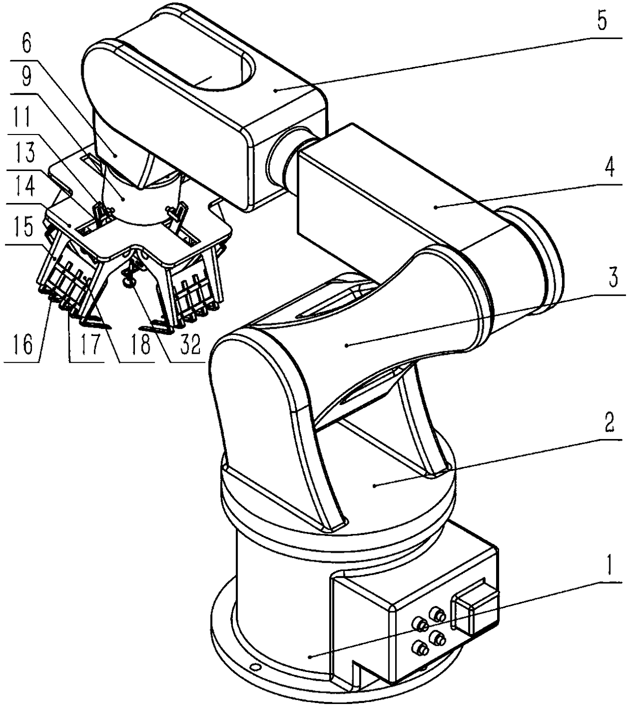
[0027] combine figure 1 , figure 2 and Figure 9 , a kind of synchronous control manipulator of the present invention, comprises base 1, rotating table 2, big arm 3, first small arm 4, second small arm 5, wrist 6, mechanical grasping device; Said mechanical grasping device passes screw fixed at the lower end of the wrist 6;

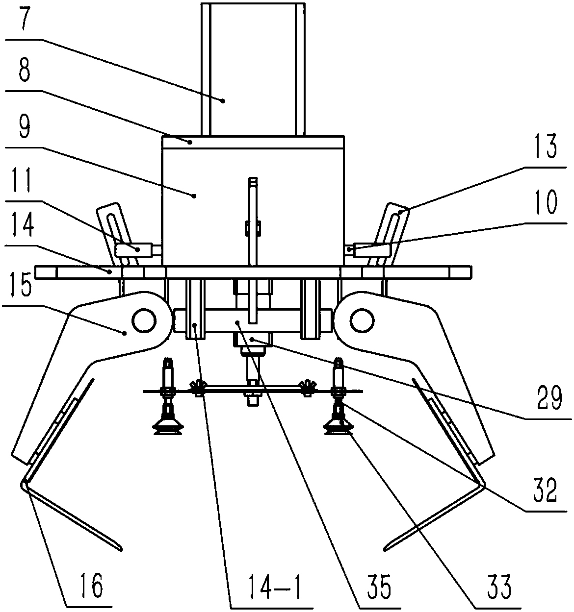
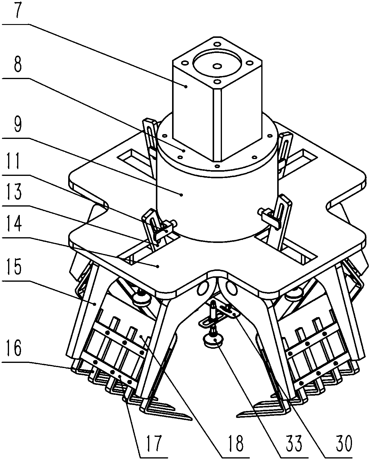
[0028] The mechanical grabbing device includes a drive mechanism, a linkage mechanism, and a mechanical claw; the drive mechanism is fixed on the lower end of the wrist 6; the drive mechanism is fixed on the upper end of the connecting platform 14 through a support frame 9; the drive mechanism and the linkage mechanism Connected, used to drive the swing of the linkage mechanism; the upper end of the connecting platform 14 is pr...


PUM


Abstract

The invention discloses a synchronous control mechanical arm. The synchronous control mechanical arm comprises a base, a rotation table, a big arm, a first small arm, a second small arm, a wrist, anda mechanical gripping device. The base is positioned by four uniformly distributed bolt holes and fixedly installed on a workbench. The rotation table is installed on the base through bolts, and rotated around a central rotation shaft of the base. The big arm is connected with the front end of the rotation table through a joint. The first small arm is connected with the front end of the big arm through the joint. The second small arm is connected with the front end of the first small arm through the joint. The wrist is connected with the front end of the second small arm through the joint. Themechanical gripping device is fixedly installed at the front end of the wrist through the bolts. The synchronous control mechanical arm is simple in structure. The mechanical gripping device uses a motor to drive mutually vertically installed rotation cams to synchronously control four claws. Bag-packed articles and box-packed articles can be captured by the synchronous control mechanical arm instead of a person. The working strength of workers is reduced, and the working efficiency is greatly improved.

Description

technical field [0001] The invention relates to an industrial robot, in particular to a synchronous control robot. Background technique [0002] At present, with the continuous improvement of industrial automation and intelligence, it is a trend for enterprises to use industrial robots to replace manual operations in order to improve work efficiency. Compared with traditional manual operations, industrial robots have a high degree of automation , can replace people to carry out some dangerous and complicated work, greatly improving work efficiency and ensuring the safety of production and processing. [0003] At present, robots are widely used in various industries, such as body welding in the automobile manufacturing industry, various workpiece handling, and product sorting on the production line. However, since the robotic hands are mostly driven by gears and cylinders, the size of the components is relatively large, and multiple motors or cylinders are required to drive ...

Claims


Application Information

Patent Timeline
Patent Type & Authority Applications(China)
IPC IPC(8): B25J15/10B25J15/02B25J9/04B25J13/08
CPCB25J9/048B25J13/082B25J15/0226B25J15/10
Inventor 武凯孙宇王强倪俊
Owner NANJING UNIV OF SCI & TECH
Why Eureka
Try Eureka