
Device and method for positioning variable-thickness preform and detecting thickness of preform

A thickness detection and prefabrication technology, applied in the field of resin matrix composite material liquid molding, can solve the problems of fiber scouring deformation, parts rich in grease, scouring deformation, etc., to ensure effectiveness and accuracy, reduce molding risks, and ensure positioning accuracy. Effect

Active Publication Date: 2018-06-29
AVIC COMPOSITES
View PDF3 Cites 12 Cited by
  • Summary
  • Abstract
  • Description
  • Claims
  • Application Information

AI Technical Summary

Problems solved by technology

However, the 2.5D / 3D braided prefabricated body formed by integral weaving of carbon fiber is formed by interweaving thousands of carbon fiber yarns. Accurate measurement by conventional detection means makes it impossible to predict the mold clamping thickness, which can easily lead to thinner thickness during RTM molding mold clamping, resulting in quality problems such as fat-rich parts or fiber erosion deformation, and also prone to thicker thickness As a result, quality problems such as inability to close the mold or excessive compaction of the preform lead to fiber buckling and deformation
When the prefabricated parts with complex shapes are molded, such as composite fan blades, due to the significant abrupt change in thickness structure, it is more difficult to predict the thickness of the prefabricated body, resulting in fat-rich, Serious quality problems such as fiber folds and erosion deformation

Method used


Image

  • Device and method for positioning variable-thickness preform and detecting thickness of preform
  • Device and method for positioning variable-thickness preform and detecting thickness of preform
  • Device and method for positioning variable-thickness preform and detecting thickness of preform

Examples


Embodiment 1

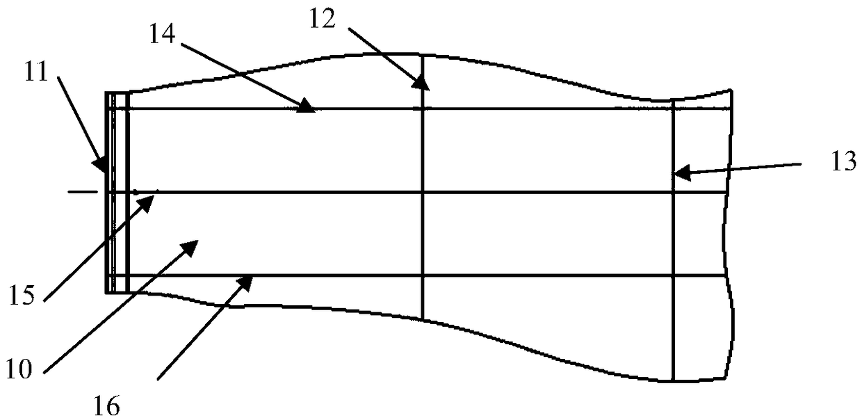
[0061] The prefabricated body 10 to be tested is a fan blade prefabricated body with a variable thickness 2.5D woven structure. The material is CCF800, and the fiber volume content of the material is 55%±3%. Among them, CCF800 is T800 grade carbon fiber with a specification of 12K produced by Shandong Weihai Development Company. The outer dimensions of the fabric and parts are: 750mm×300mm×(1.5~60mm) (length×width×height), and the distances of 0mm, 380mm and 680mm in the longitudinal direction of the surface of the prefabricated body 10 are pre-set with glass fiber weaving. Lines 11, transverse positioning lines 12 and transverse positioning lines 13 are preformed with glass fiber braided longitudinal positioning lines 14, longitudinal positioning lines 15 and longitudinal positioning lines 16 at distances of 0, 150 mm, and 250 mm in the width direction of the surface of the prefabricated body 10. . The specific implementation steps are as follows:

[0062] 1) The profile too...

Embodiment 2

[0072] The prefabricated body 10 to be tested is a variable thickness 3D woven structure fan blade prefabricated body, the material is CCF800, and the fiber volume content of the material is 53%±3%; CCF800 is a T800 grade carbon fiber fabric with a specification of 6K produced by Shandong Weihai Development Company , the external dimensions of the parts are: 720mm×300mm×(3~50mm) (length×width×height), and the distances of 0mm, 190mm, 380mm, 530mm and 680mm in the surface length direction of the prefabricated body 10 are pre-set with glass fiber weaving The horizontal positioning line 11, the horizontal positioning line 17, the horizontal positioning line 12, the horizontal positioning line 18 and the horizontal positioning line 13 are preformed with a longitudinal positioning line 15 which adopts glass fiber weaving in the width direction 150mm of the prefabricated body 10 surface. The specific implementation steps are as follows:

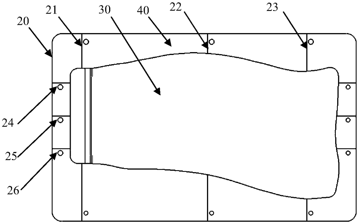
[0073] 1) The profile tooling 20 is composed...


PUM


Abstract

The invention belongs to a liquid molding technology of the resin-based composite material, and relates to a device and method for positioning a variable-thickness preform and detecting the thicknessof the preform. The device comprises a molded surface tool, transverse clamping plates and longitudinal clamping plates, wherein the molded surface tool is a flat plate and is divided into a molded surface area and a positioning area, machining is carried out on the molded surface area by taking the lower surface of the preform as a benchmark, transverse scribed lines are machined on the positioning area based on the transverse positioning lines on the preform, and longitudinal scribed lines are machined on the positioning area based on the longitudinal positioning lines on the preform; and machining is carried out by taking the upper surface of the preform as the detection surfaces of the transverse clamping plates and the longitudinal clamping plates, the transverse clamping plates and the longitudinal clamping plates are positioned on the positioning area of the molded surface area through pin holes, and after positioning, the center lines of the transverse clamping plates are aligned with the transverse scribed lines on the positioning area, and the center lines of the longitudinal clamping plates are aligned with the longitudinal scribed lines on the positioning area. According to the device, the molded surface state of the complex-structured preform can be pre-judged and processed before mold closing, and the yield of the composite material workpieces is remarkably improved.

Description

technical field [0001] The invention belongs to the liquid forming technology of resin-based composite materials, and relates to a device and method for positioning and thickness detection of a variable-thickness prefabricated body. Background technique [0002] Carbon fiber reinforced resin-based composite materials have unique advantages such as light weight, high specific strength, high specific modulus, good fatigue fracture resistance, corrosion resistance, and easy large-area integral forming. The amount of key materials used in equipment has also become one of the symbols of the advanced nature of aviation equipment. [0003] Resin transfer molding technology, referred to as RTM molding technology (Resin Transfer Molding) is a liquid molding composite material manufacturing technology widely used in aviation, aerospace and other fields in recent years. The principle is to lay dry fiber preforms designed according to the performance and structural requirements in the ...

Claims


Application Information

Patent Timeline
IPC IPC(8): B29C70/48B29C70/54
CPCB29C70/48B29C70/54
Inventor 刘强黄峰马金瑞赵龙
Owner AVIC COMPOSITES
Learn More