

Automatic horizontal rotation device for wind power spindle flange plate
A wind power main shaft and flange technology, which is applied in the direction of hoisting device, conveyor control device, transportation and packaging, etc., can solve the problems of high cost of large-scale driving, increase production cost, low efficiency, etc., and achieve the goal of reducing labor intensity and saving energy. Consuming, error-prone effects
- Summary
- Abstract
- Description
- Claims
- Application Information
AI Technical Summary
Problems solved by technology
Method used
Image

Examples
Embodiment 1
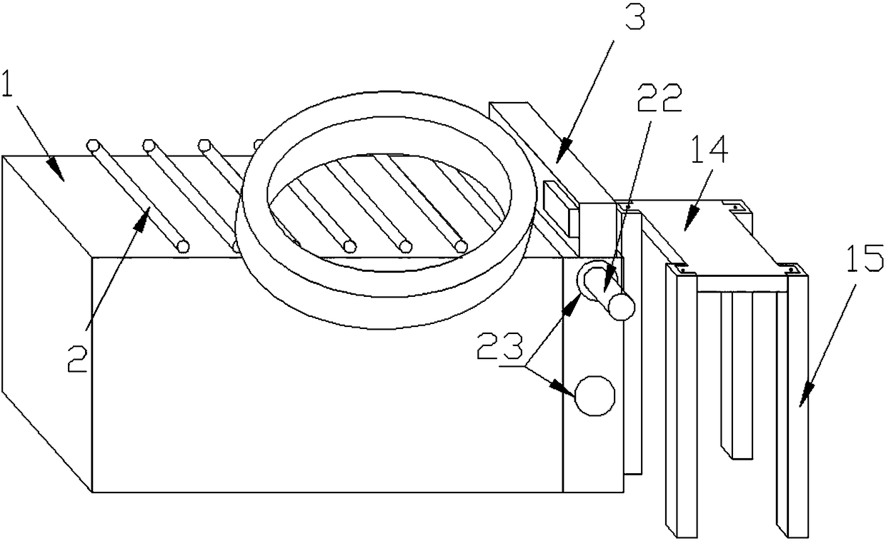
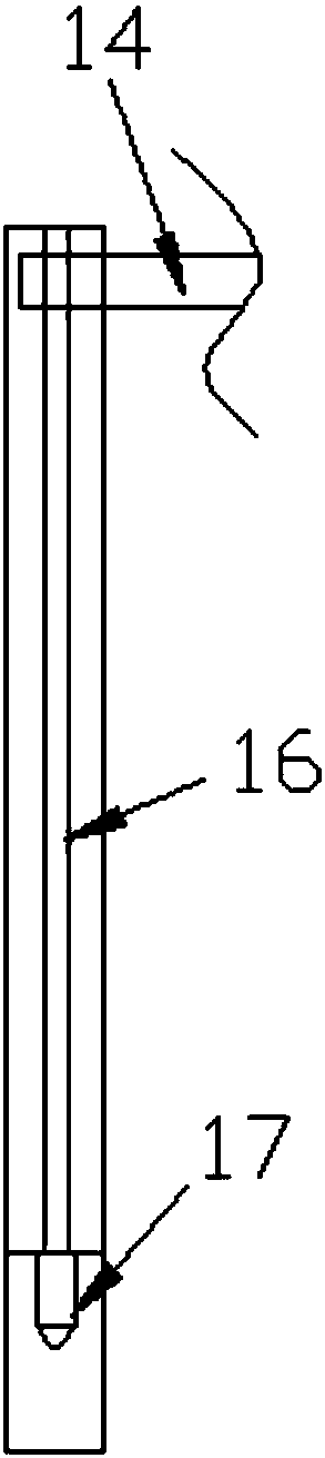
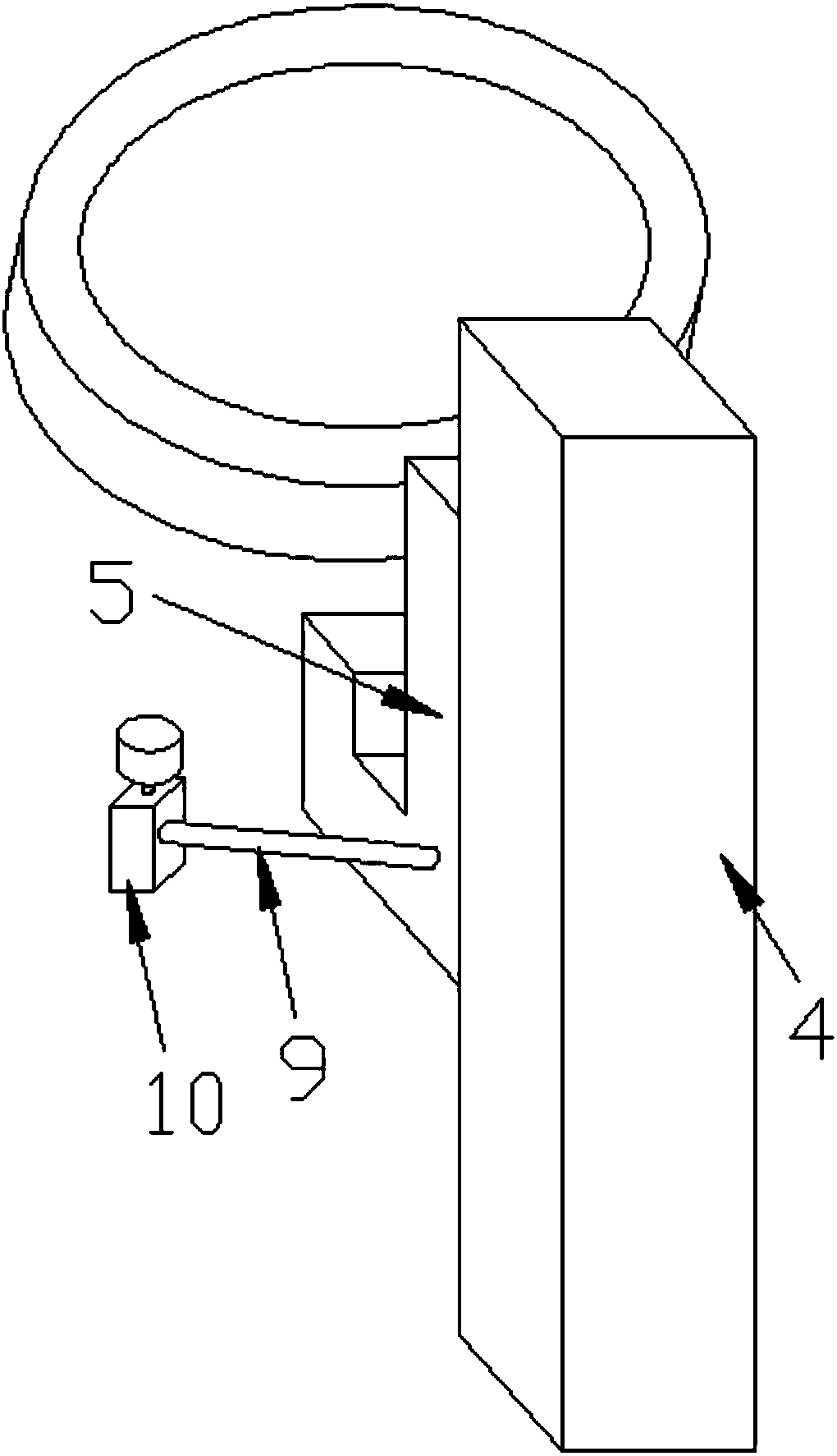
[0039] Such as Figure 1 to Figure 6 as shown ( figure 1 The flange lifting device and the flange turning device are not shown; image 3 , Figure 4 Another support opposite to it is not shown), the present invention is a wind power main shaft flange automatic translation device, including a frame 1, a flange conveying device 2 is provided on the working surface of the frame 1, and the frame 1 One end of the conveying direction is provided with a lifting type limit baffle 3, and the height of the limit baffle 3 does not exceed the height of the flange; it also includes a flange lifting mechanism, and the flange lifting mechanism is arranged on both sides of the flange conveying device 2, and Located below the flange, the flange lifting mechanism is provided with a rotary drive mechanism that drives the flange to rotate; it also includes a flange storage rack 15 with a flange storage table 14, and the flange storage rack 15 is provided with a drive flange storage table 14 th...
Embodiment 2
[0041] The difference from Embodiment 1 is that, as Figure 7 As shown, the lifting lead screw and the drive motor are also arranged under the limit baffle, so that all operations are fully mechanized without manual work and fully automated.
Embodiment 3
[0043] The difference from Embodiment 1 is that, as Figure 8 As shown (flange lifting device and flange rotating device, limit pin, flange storage rack are not shown), the working surface of frame 1 is inclined, and the width of the conveying roller is less than the diameter of the flange.
PUM
 Abstract
Description
Claims
Application Information