Sludge drying device and sludge drying method
A sludge drying and sludge technology, applied in the direction of dewatering/drying/concentrating sludge treatment, can solve the problems of low direct combustion efficiency and high energy consumption, achieve significant drying effect, avoid secondary pollution, and reduce water content rate effect
- Summary
- Abstract
- Description
- Claims
- Application Information
AI Technical Summary
Problems solved by technology
Method used
Image

Examples
Embodiment Construction
[0025] The technical solutions of the present invention will be further described below in conjunction with the accompanying drawings and through specific implementation methods.
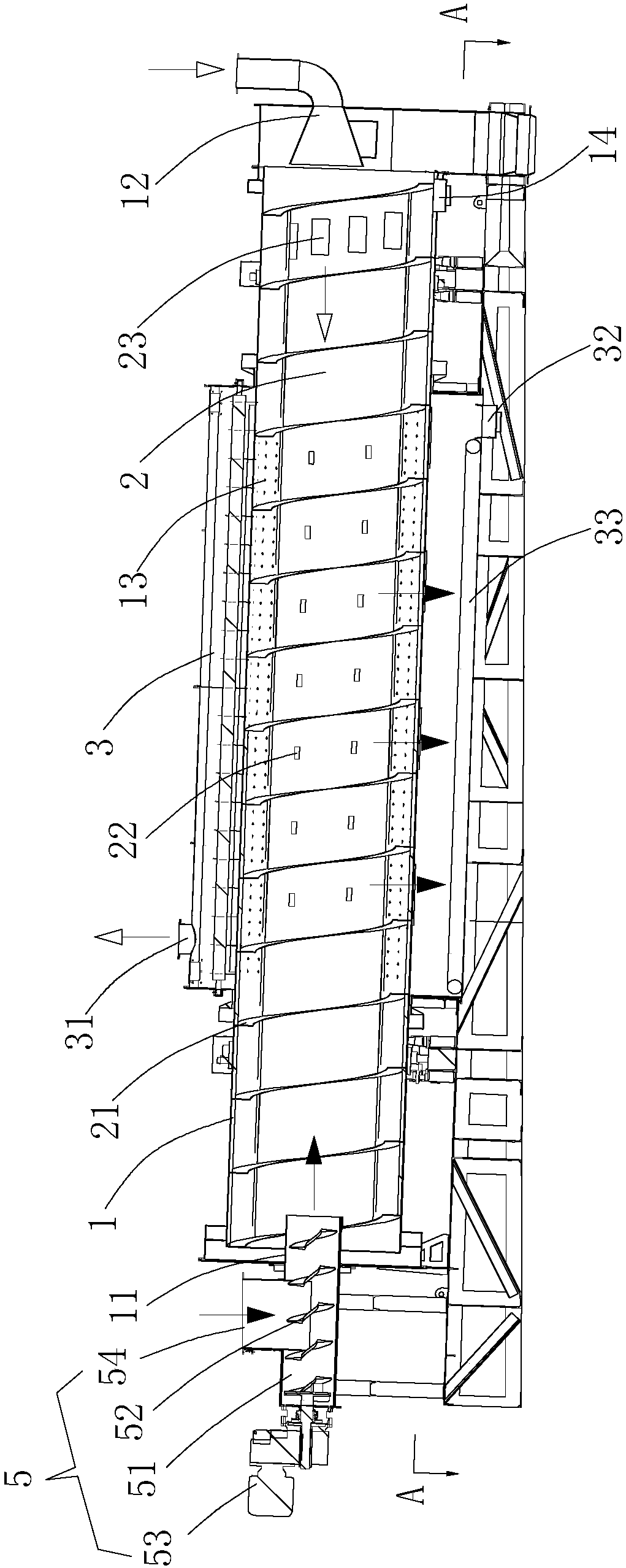
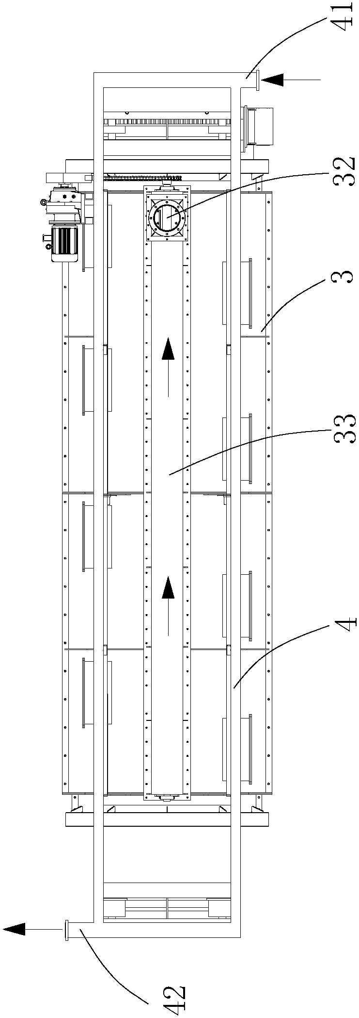
[0026] see figure 1 and 2 As shown, this embodiment provides a sludge drying device, which is used for drying treatment of wet waste before incineration, including sludge, which includes an inclined drying cylinder 1, and the inclination angle of the drying cylinder 1 is 2 ~5 degrees is appropriate, the high end of the drying cylinder 1 is provided with a material inlet 11, the low end of the drying cylinder 1 is provided with a flue gas inlet 12, and a hollow shaft 2 is installed in the drying cylinder 1, and the hollow shaft 2 One end is docked with the material inlet 11, and the other end is docked with the flue gas inlet 12. The hollow shaft 2 is spirally and spaced around with deflectors 21. The middle part of the hollow shaft 2 is provided with a number of screen holes 22. The wall of the dry...
PUM
 Abstract
Description
Claims
Application Information
 - Generate Ideas
- Intellectual Property
- Life Sciences
- Materials
- Tech Scout
- Unparalleled Data Quality
- Higher Quality Content
- 60% Fewer Hallucinations
Browse by: Latest US Patents, China's latest patents, Technical Efficacy Thesaurus, Application Domain, Technology Topic, Popular Technical Reports.
© 2025 PatSnap. All rights reserved.Legal|Privacy policy|Modern Slavery Act Transparency Statement|Sitemap|About US| Contact US: help@patsnap.com