
System and method for adjusting exhaust valve timing

An exhaust valve and timing technology, which is applied in the direction of electrical control, machine/engine, output power, etc., can solve the problems of opening time error, reduce engine power, increase engine emission, etc., and achieve improved exhaust valve timing control Effect

Active Publication Date: 2022-04-29
FORD GLOBAL TECH LLC
View PDF6 Cites 0 Cited by
  • Summary
  • Abstract
  • Description
  • Claims
  • Application Information

AI Technical Summary

Problems solved by technology

Manufacturing tolerances may cause errors between the commanded intake and / or exhaust valve opening times and the actual intake and / or exhaust valve opening times from vehicle to vehicle
Errors in cylinder valve timing can increase engine emissions or reduce engine power

Method used


Image

  • System and method for adjusting exhaust valve timing
  • System and method for adjusting exhaust valve timing
  • System and method for adjusting exhaust valve timing

Examples


Embodiment Construction

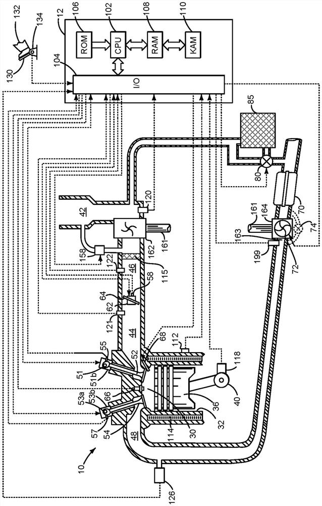
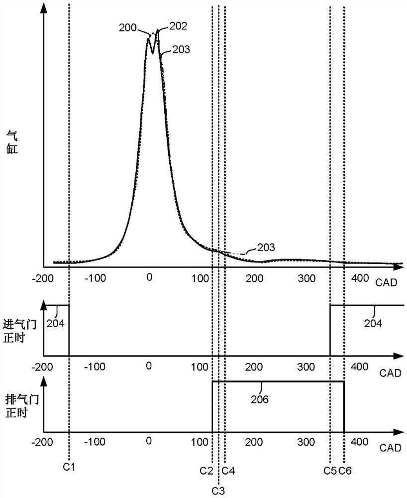
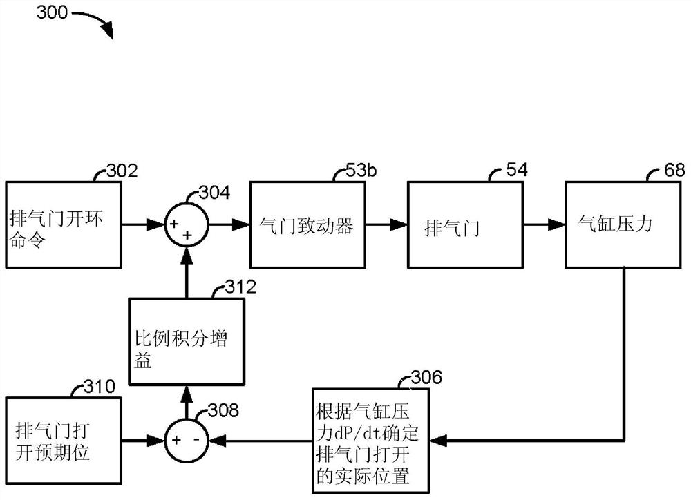
[0012] The present specification relates to improving combustion within a cylinder of an internal combustion engine in response to pressure sensor feedback from a pressure sensor located in the cylinder. figure 1 Exemplary cylinders of an internal combustion engine are shown. figure 2 An example cylinder pressure profile captured via a cylinder pressure sensor is shown. exist image 3 A block diagram of an exemplary valve timing controller is shown in . Finally, in Figure 4 A method of operating an engine with variable valve timing is shown in .

[0013] see figure 1 , including multiple cylinders (one of which is in figure 1 An internal combustion engine 10 shown in ) is controlled by an electronic engine controller 12 . Electrical connections are indicated by dashed lines. Engine 10 includes combustion chamber 30 and cylinder walls 32 with piston 36 positioned therein and connected to crankshaft 40 . Combustion chamber 30 is shown communicating with intake manifold...


PUM


Abstract

The present invention relates to systems and methods for adjusting exhaust valve timing. Methods and systems for adjusting exhaust valve timing of an engine are described. In one example, the exhaust valve timing of a compression-ignition engine is adjusted in response to a difference between a commanded exhaust valve opening timing and an actual exhaust valve opening timing, the actual exhaust valve opening timing being a function of cylinder The pressure is ok.

Description

technical field [0001] The present invention relates to systems and methods for adjusting exhaust valve timing. Background technique [0002] Compression ignition engines may be equipped with adjustable valve timing systems to increase engine efficiency and power. An adjustable valve timing system may consist of one or more camshafts, a cam phasing actuator, and a timing chain connecting the one or more camshafts to the engine crankshaft. Cam phase actuators may adjust the position of one or more camshafts relative to the position of the camshafts on which lobes operate intake and / or exhaust valves of engine cylinders. Manufacturing tolerances may cause errors between the commanded intake and / or exhaust valve opening times and the actual intake and / or exhaust valve opening times from vehicle to vehicle. Errors in cylinder valve timing can increase engine emissions or reduce engine power. Therefore, it may be desirable to control actual cylinder valve timing to commanded v...

Claims


Application Information

Patent Timeline
Patent Type & Authority Patents(China)
IPC IPC(8): F02D13/02F02D41/00F02D41/02F02D41/38
CPCF02D13/0249F02D41/0002F02D41/0007F02D41/024F02D41/38F02D41/1402F02D41/1446F02D35/023F02D2250/14F02D41/1461F01L2800/00F01L1/344F02B37/00F02D41/40Y02T10/12Y02T10/40F02D2200/024F02D2200/0802
Inventor E·M·库尔茨B·L·富尔顿
Owner FORD GLOBAL TECH LLC
Learn More