A thermal power plant cogeneration and compressed air energy storage complementary integrated system

A technology for compressed air energy storage and cogeneration

Active Publication Date: 2020-03-24
INST OF ENGINEERING THERMOPHYSICS - CHINESE ACAD OF SCI
View PDF7 Cites 0 Cited by
  • Summary
  • Abstract
  • Description
  • Claims
  • Application Information

AI Technical Summary

Problems solved by technology

[0005] In view of the lack of thermoelectric decoupling capability of existing thermal power cogeneration units and the optimization of the cold and hot water tank system of the adiabatic compressed air energy storage system, at the same time, the excessive wind power, photovoltaic and other renewable energy sources in the three north regions of my country have nowhere to be consumed To solve the problem of storage, the present invention provides a thermal power cogeneration and compressed air energy storage complementary integrated system, which couples the thermal power cogeneration system and the adiabatic compressed air energy storage system, so that the thermal power unit can complete thermoelectric decoupling, and the The excess electric energy is stored in the adiabatic compressed air energy storage system, and at the same time, it can get rid of the limitation of the hot and cold water tanks of the adiabatic compressed air energy storage system through the coupling of heat flow, reducing system investment and land occupation

Method used


Image

  • A thermal power plant cogeneration and compressed air energy storage complementary integrated system

Examples


Embodiment Construction

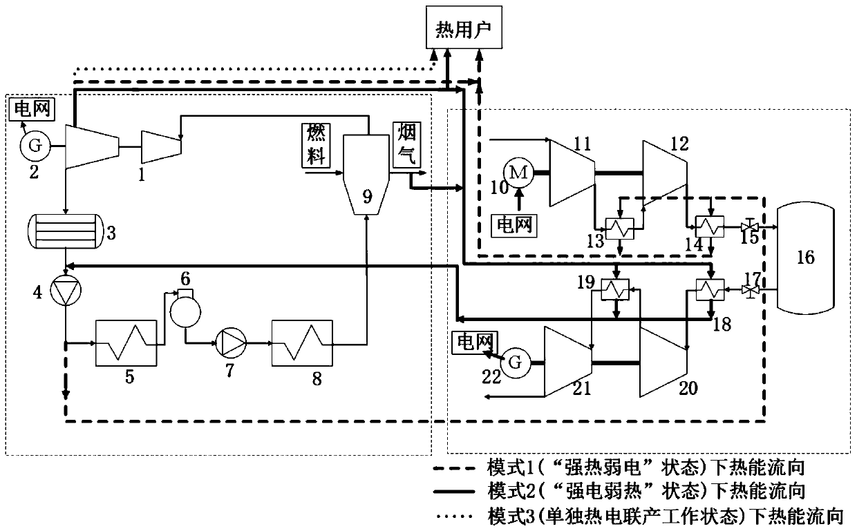
[0024] In order to make the object, technical solution and advantages of the present invention clearer, the present invention will be further described in detail below with reference to the accompanying drawings and examples. It should be understood that the specific embodiments described here are only used to explain the present invention, not to limit the present invention. In addition, the technical features involved in the various embodiments of the present invention described below can be combined with each other as long as they do not constitute a conflict with each other.

[0025] In order to make the purpose, technical solution and advantages of the present invention clearer, the following describes in detail the operation process of the thermal power plant cogeneration and compressed air energy storage complementary integrated system with reference to the accompanying drawings and examples. It should be noted that the following are only preferred embodiments of the pr...


PUM


Abstract

The invention discloses a thermal power cogeneration and compressed air energy storage complementary integrated system, which includes a thermal power cogeneration system and an adiabatic compressed air energy storage system, which can simultaneously solve the problem of heat load and electric load supply and demand in the heating season in northern my country. Balanced situation, to accommodate more renewable electricity grid. At the same time, avoid high-grade energy loss caused by high heating and extraction parameters of cogeneration units, compression heat loss of compressor units, and cancel hot and cold water tanks. When the heat load is high and the electricity load is low, the system is in the state of "strong heat and weak electricity". At this time, the compressed air energy storage unit stores electricity and releases heat, and the combined heat and power unit and the compressed air energy storage Heat supply; when the electric load is high and the heat load is low, the system is in the state of "strong electricity and weak heat". At this time, the compressed air energy storage unit absorbs the heat from the cogeneration unit and releases electricity at the same time; The unit works alone, and the heating and power supply can be adjusted within a small range.

Description

technical field [0001] The invention belongs to the technical field of energy storage and energy saving, and relates to a compressed air energy storage system, in particular to a complementary integrated system of thermal power cogeneration and compressed air energy storage in a thermal power plant. The heat of steam and the waste heat of boiler exhaust smoke realize the efficient storage and utilization of electric energy and thermal energy. Background technique [0002] Compressed air energy storage can realize large-capacity and long-term electric energy storage, and adiabatic compressed air energy storage is an advanced energy storage system that does not depend on fuel. During operation, a large amount of heat of compression will be generated. Due to the limitation of the heat transfer temperature difference of the heat exchanger, this part of the heat of compression cannot be completely transferred to the compressed air in the energy release process, so the temperature...

Claims


Application Information

Patent Timeline
Patent Type & Authority Patents(China)
IPC IPC(8): F25B41/00F24D3/10F24D3/18F22D1/50F01K17/02F04B39/00F01D15/10F01B23/10F25B41/40
CPCF01B23/10F01D15/10F01K17/02F04B39/00F22D1/50F24D3/10F24D3/18F24D2200/13F25B41/40Y02E20/14Y02B30/00
Inventor 郭丛徐玉杰郭欢张新敬陈海生
Owner INST OF ENGINEERING THERMOPHYSICS - CHINESE ACAD OF SCI
Why Eureka
Try Eureka