Damage detection equipment

A technology for damage detection and equipment, applied in the direction of testing dielectric strength, using radiation for material analysis, etc., can solve problems such as the inability to detect mechanical damage of electrical components, improve power supply reliability, improve power supply reliability, and clear image quality Effect

Inactive Publication Date: 2018-06-29
STATE GRID BEIJING ELECTRIC POWER +1
View PDF6 Cites 3 Cited by
  • Summary
  • Abstract
  • Description
  • Claims
  • Application Information

AI Technical Summary

Problems solved by technology

[0004] The main purpose of the present invention is to provide a damage detection device to solve the prob

Method used


Image

  • Damage detection equipment
  • Damage detection equipment
  • Damage detection equipment

Examples


Embodiment Construction

[0022] It should be noted that, in the case of no conflict, the embodiments in the present application and the features in the embodiments can be combined with each other. The present invention will be described in detail below with reference to the accompanying drawings and examples.

[0023] It should be pointed out that the following detailed description is exemplary and intended to provide further explanation to the present application. Unless defined otherwise, all technical and scientific terms used herein have the same meaning as commonly understood by one of ordinary skill in the art to which this application belongs.

[0024] It should be noted that the terminology used here is only for describing specific implementations, and is not intended to limit the exemplary implementations according to the present application. As used herein, unless the context clearly dictates otherwise, the singular is intended to include the plural, and it should also be understood that wh...


PUM


Abstract

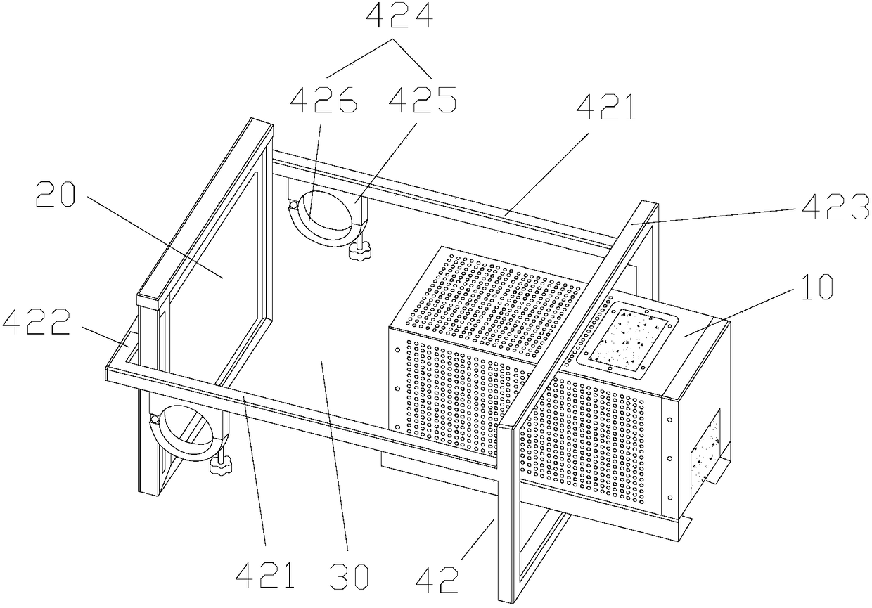
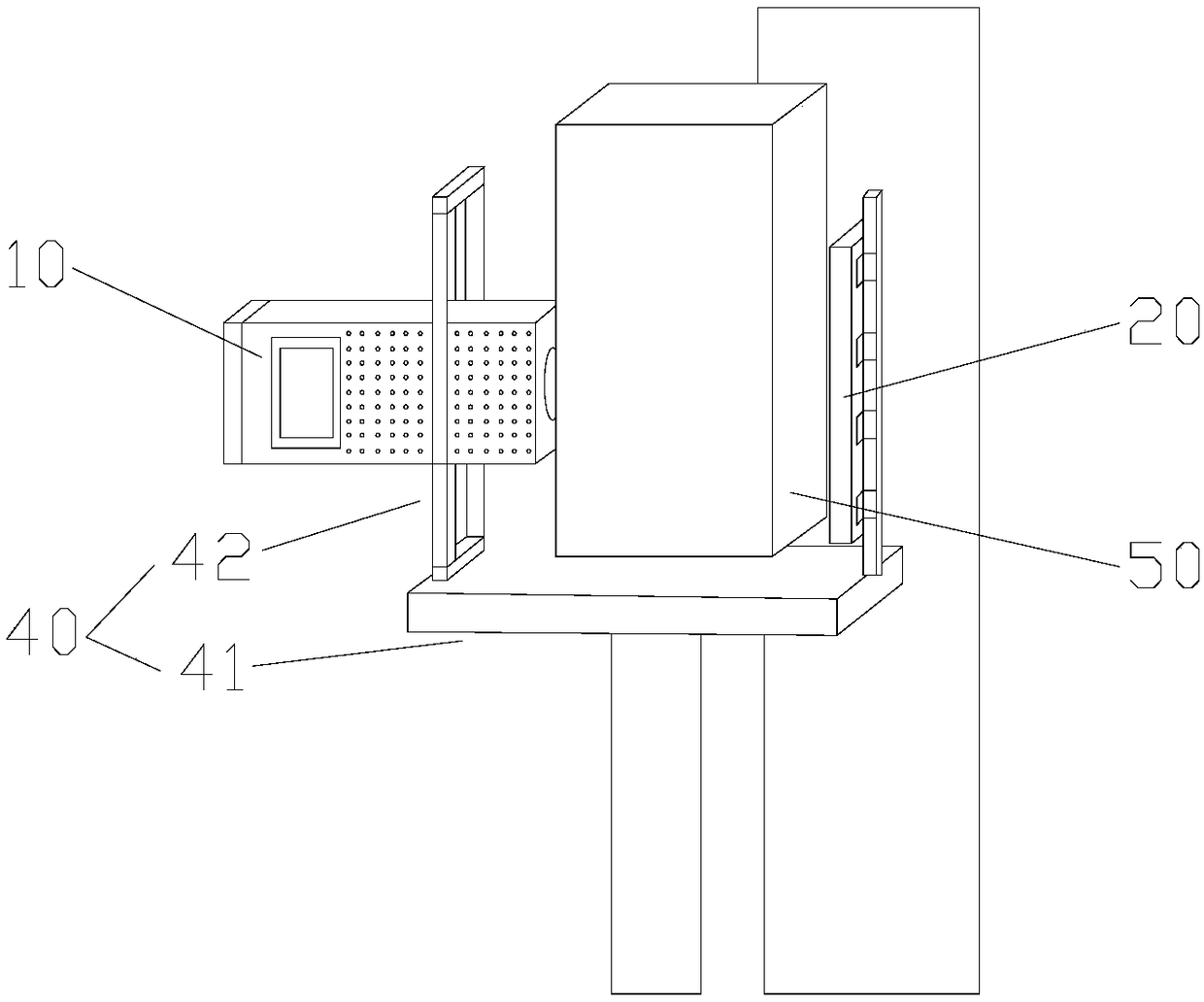
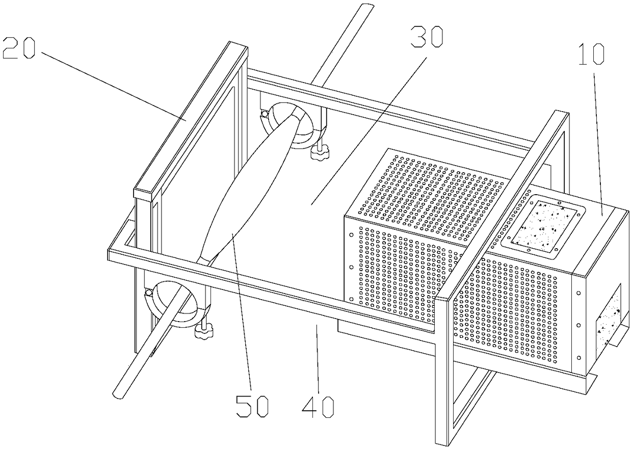
The invention provides damage detection equipment, which comprises an X-ray generating device and an imaging device, wherein the X-ray generating device is used for sending out X rays; the imaging device and the X-ray generating device are in opposite arrangement; an accommodating space used for accommodating an electric appliance component to be detected is formed between the X-ray generating device and the imaging device so that the X rays pass through the electric appliance component positioned in the accommodating space and is then imaged on the imaging device. The damage detection equipment solves the problem that the detection equipment in the prior art cannot be used for detecting the inside mechanical damage of the electric appliance component.

Description

technical field [0001] The invention relates to the technical field of electric equipment, in particular, to a damage detection equipment. Background technique [0002] With the continuous promotion and application of power distribution automation functions by power companies, whether the closed equipment in the power field can operate normally will greatly affect the successful application of power distribution automation. The operation and maintenance of closed equipment in the power field can only be detected by partial discharge through ultrasonic detection devices. There is no detection method when the internal mechanical damage does not form partial discharge, and the internal mechanical damage of the switch on the pole cannot be detected, resulting in O&M Work is in a blind spot. [0003] At present, X-ray digital imaging non-destructive testing pilots apply 35kV and above power transformation and power transmission systems with fully enclosed structure power equipme...

Claims


Application Information

Patent Timeline
IPC IPC(8): G01N23/04G01R31/12
CPCG01N23/18
Inventor 任立新路遥陈飞宇刘玥刘长勇任增安梁武震
Owner STATE GRID BEIJING ELECTRIC POWER
Why Eureka
Try Eureka