Deep sea broadband target depth estimation method based on stripe interference structure

A technology of target depth and interference structure, which is applied in the field of deep-sea broadband target depth estimation based on fringe interference structure, and can solve the problems of less application of waveguide invariants and other problems.

Active Publication Date: 2018-06-29
NORTHWESTERN POLYTECHNICAL UNIV
View PDF10 Cites 22 Cited by
  • Summary
  • Abstract
  • Description
  • Claims
  • Application Information

AI Technical Summary

Problems solved by technology

The waveguide invariant theory is widely used in the shallow sea environment, but in the deep sea environment the waveguide invariant changes with the signal center f

Method used


Image

  • Deep sea broadband target depth estimation method based on stripe interference structure
  • Deep sea broadband target depth estimation method based on stripe interference structure
  • Deep sea broadband target depth estimation method based on stripe interference structure

Examples


Embodiment Construction

[0055] Now in conjunction with embodiment, accompanying drawing, the present invention will be further described:

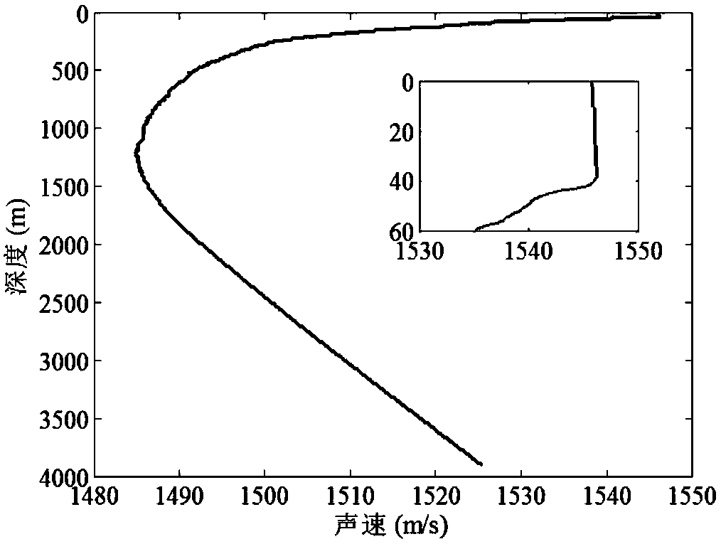
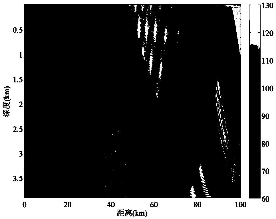
[0056] This example figure 1 The sound velocity profile of the experimental sea area is given, the water depth is 3904m, and the depth of the mixed layer is 40m. The bottom of the sea is basically flat. The receiving array is a 16-element vertical line array, located on the seabed, the array element spacing is 4m, and the depth of the array element center is 3700m. The seabed sound velocity, density and attenuation coefficient are 1560m / s and 1.6g / cm respectively 3 and 0.2dB / λ. figure 2 It is the propagation loss map in this environment. It can be seen that the typical deep sea acoustic propagation path has lower propagation loss near the seabed of 20 kilometers and 70 kilometers, and the received underwater acoustic signal has a higher signal-to-noise ratio. Object depth estimation is accomplished through the following four steps:

[0057] Step 1 assumes ...


PUM


Abstract

The invention relates to a deep sea broadband target depth estimation method based on a fringe interference structure, which comprises a vertical linear array and is conducive to the extraction of thebroadband interference fringe structure. The deep sea broadband target depth estimation method provided by the invention has the benefits that first, the vertical linear array is laid in water, and abroadband signal transmitted by a motion target is received; meanwhile, in an experimental environment, the simulation of interference strip structures with different sound source depths is performedby utilizing a sound field model, experiment and simulated interference fringe tracking are performed by utilizing an extended Kalman filter, tracked fringe position and quantity information is substituted into a cost function, and the cost function is minimized; at this moment, the corresponding sound source depth is a target estimation depth. The deep sea broadband target depth estimation method provided by the invention has the following advantages that the complex sound field model calculation is not needed; an array beam is utilized for output, so that the signal-to-noise ratio is improved; the robustness is good, and the change along with the environment is small; a hydrophone is positioned at the bottom of a sea and is convenient to lay; a submersible beacon can stably work for a long time.

Description

technical field [0001] The invention belongs to the fields of underwater acoustic engineering, marine engineering, sonar technology and the like, and relates to a method for estimating the depth of a deep-sea broadband target based on a fringe interference structure, which is suitable for positioning a broadband moving target with a depth less than 1000 meters in a deep-sea environment. Background technique [0002] Passive localization of targets is one of the hot issues in underwater acoustic research in recent years. The positioning methods widely used in sonar systems include matching field positioning technology, methods based on normal wave models, positioning methods based on multi-path arrival structures, and positioning methods based on interference fringes. Their characteristics are: (1) Matching field processing utilizes ocean environment parameters and acoustic propagation channel characteristics, requires sufficient sampling of the acoustic field, and requires t...

Claims


Application Information

Patent Timeline
IPC IPC(8): G01S15/66G01S15/00
CPCG01S15/006G01S15/66
Inventor 杨坤德徐丽亚段睿刘鸿杨秋龙
Owner NORTHWESTERN POLYTECHNICAL UNIV
Why Eureka
Try Eureka