Organic electroluminescence device

An electroluminescence device and electroluminescence technology, which are applied in the direction of electro-solid devices, electrical components, semiconductor devices, etc., can solve the problems of low luminous efficiency and large driving voltage of the device, and achieve the improvement of luminous efficiency, reduction of driving voltage, and reduction of voltage. Effect

Active Publication Date: 2018-06-29
KUNSHAN GO VISIONOX OPTO ELECTRONICS CO LTD
View PDF8 Cites 11 Cited by
  • Summary
  • Abstract
  • Description
  • Claims
  • Application Information

AI Technical Summary

Problems solved by technology

[0004] In view of this, the embodiments of the present invention are dedicated to providing an organic electroluminescent device to solve the problems of high device driving voltage and low luminous efficiency caused by the monochromatic light-emitting layer being composed of a single light-emitting material.

Method used


Image

  • Organic electroluminescence device
  • Organic electroluminescence device
  • Organic electroluminescence device

Examples


Embodiment 1

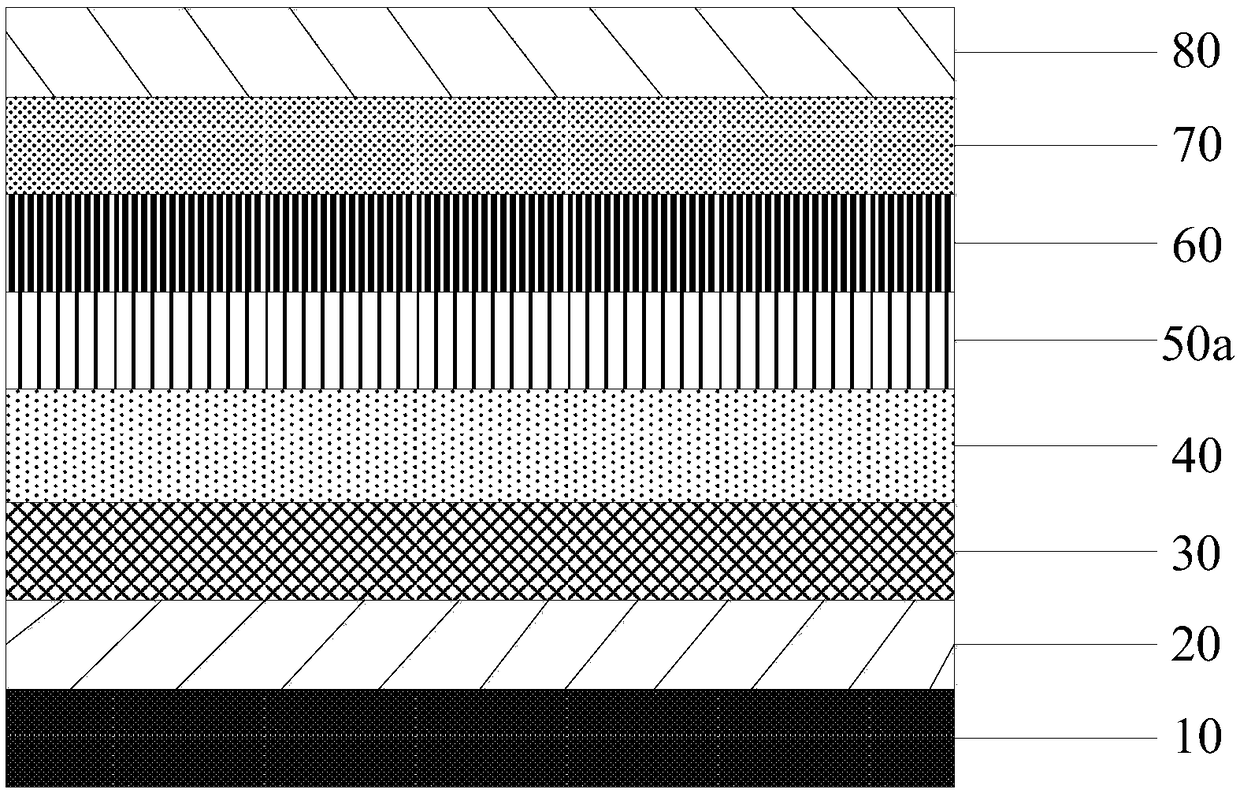
[0058] The host material of the blue light-emitting layer of the organic electroluminescent device in this example is premixed with a donor host material and an acceptor host material with a mass ratio of 1:5. The structure of the device is as follows figure 1 shown. The host material of the monochromatic light-emitting layer 50a is an exciplex (wherein, the donor host material is 1-1, and the acceptor host material is 2-1), and the guest material doped in the host material is a blue fluorescent material 3-1 .

[0059] The device structure of this embodiment is as follows:

[0060] Anode (ITO, 20nm) / hole injection layer (HAT-CN, 10nm) / hole transport layer (NPB, 10nm) / donor host material (1-1, 10nm): acceptor host material (2-1, 10nm): 5% blue fluorescent material (3-1) / electron transport layer (TPBi, 10nm) / electron injection layer (Bphen, 10nm) / cathode (Al, 10nm)

Embodiment 2

[0071] Example 2 The difference between this example and Example 1 is that the mass ratio of the donor host material to the acceptor host material is 5:5.

Embodiment 3

[0072] Example 3 The difference between this example and Example 1 is that the mass ratio of the donor host material to the acceptor host material is 7.5:2.5.


PUM


Abstract

The invention provides an organic electroluminescence device. The device solves the problem that the driving voltage of devices is high, and the luminous efficiency is low since a monochromatic lightemitting layer is made of a single luminescent material. The provided organic electroluminescence device includes a monochromatic light emitting layer, the monochromatic light emitting layer is made of double-subject materials and doped object materials, the double-subject materials comprise the donor subject material and the receptor subject material, and the donor subject material and the receptor subject material form an exciplex.

Description

technical field [0001] The invention relates to the technical field of display devices, in particular to an organic electroluminescence device. Background technique [0002] Organic electroluminescent devices are self-luminous devices. Due to their characteristics of wide viewing angle, high contrast, high brightness, low driving voltage, fast response time, and light and thin panels, they have attracted extensive attention as the next generation of flat panel display devices. [0003] The light-emitting mechanism of organic electroluminescent devices belongs to the carrier injection type, that is, when a voltage is applied to the light-emitting layer sandwiched between the anode layer and the cathode layer, the holes injected from the anode layer flow through the hole-transport layer and move to the light-emitting layer. , electrons injected from the cathode layer flow through the electron transport layer and move to the light emitting layer. The holes and electrons that a...

Claims


Application Information

Patent Timeline
Patent Type & Authority Applications(China)
IPC IPC(8): H01L51/50H01L51/54
CPCH10K50/121H10K50/12H10K50/11H10K2101/10
Inventor 王荷丹张晓珍何麟
Owner KUNSHAN GO VISIONOX OPTO ELECTRONICS CO LTD
Why Eureka
Try Eureka