
High-voltage battery discharge circuit and control method thereof

A discharge circuit, high-voltage battery technology, applied in battery/fuel cell control devices, control devices, circuit breaker testing, etc., can solve problems such as battery pack structural damage, loss of battery pack components, and risk of fire, and improve safety. performance and reliability, improve use efficiency, and facilitate subsequent investigations

Active Publication Date: 2018-07-06
ZHEJIANG GEELY AUTOMOBILE RES INST CO LTD +1
View PDF8 Cites 16 Cited by
  • Summary
  • Abstract
  • Description
  • Claims
  • Application Information

AI Technical Summary

Problems solved by technology

Although this method does not need to add additional hardware circuits, it has the advantages of short detection time and low cost, but the detection method has the following problems: 1. The hardware circuit used in this method is under the condition that the main positive contactor KM1 is sintered or the control signal is abnormal. In the process of closing the main negative contactor KM2, a very large inrush current will be formed for a short time through the pre-charged capacitor C. This current is extremely destructive, ranging from damage to the main contactor and power lines, to serious damage to the battery pack. The internal structure is damaged, forming a strong current arc and sparking, which makes the internal components of the battery pack out of control, posing a risk of fire, and poor safety in use; 2. This control method can only judge whether the main and negative contactors are sintered. Unable to detect, there is a problem of poor security

Method used


Image

  • High-voltage battery discharge circuit and control method thereof
  • High-voltage battery discharge circuit and control method thereof
  • High-voltage battery discharge circuit and control method thereof

Examples


Embodiment Construction

[0027] The following are specific embodiments of the present invention and in conjunction with the accompanying drawings, the technical solutions of the present invention are further described, but the present invention is not limited to these embodiments.

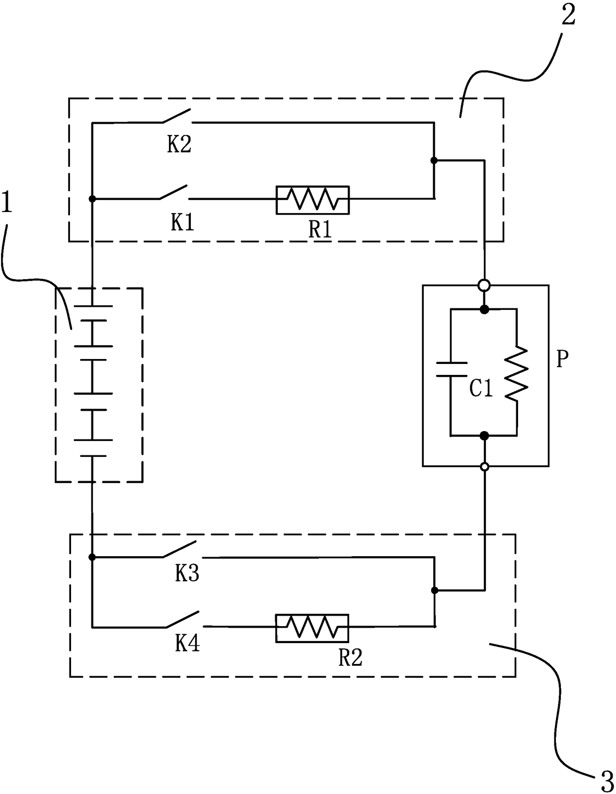
[0028] Such as figure 1 As shown, this high-voltage battery discharge circuit includes a battery pack 1, a positive pre-charging circuit 2, a negative pre-charging circuit 3, and a power element P with a capacitive load C1. The positive load C1 and the negative pre-charging circuit 3 are connected in series, the negative pre-charging circuit 3 is connected to the negative pole of the battery pack 1, the positive pre-charging circuit 2 includes the positive contactor K2, the pre-charging contactor K1 and the pre-charging resistor R1, the pre-charging contact Connector K1 and pre-charging resistance R1 are connected in series and connected in parallel at both ends of positive contactor K2. Negative pre-charging circuit 3 inc...


PUM


Abstract

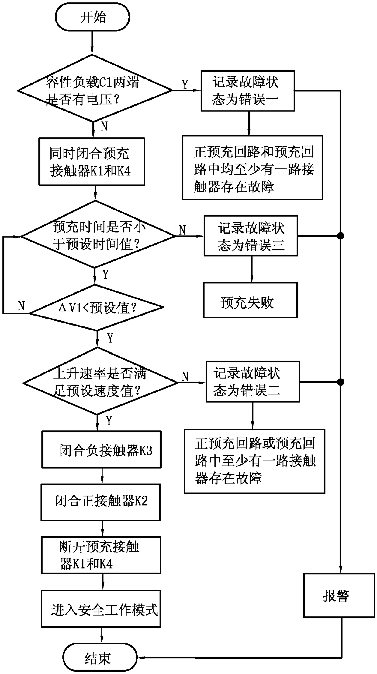
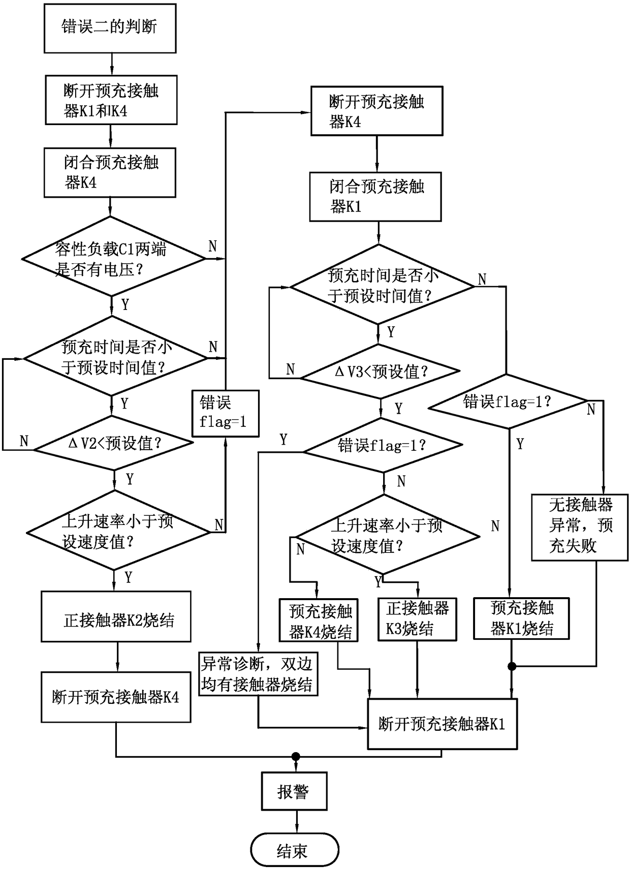
The invention provides a high-voltage battery discharge circuit and control method thereof, and belongs to the technical field of high-voltage battery solving the problem of poor safety in the prior art. The control method for the discharge circuit of the high-voltage battery comprises the following steps of: detecting whether the two ends of the capacitive load C1 are showed voltage, if so, recording the fault state as error I and alarming; if no voltage is showed, the pre-charging contactor K1 and the pre-charging contactor K4 are controlled to be closed simultaneously, detecting the voltageon the two ends of the capacitive load C1 in the suction process and recording the pre-charging time, and calculating the real-time rising rate of voltage on the two ends of the capacitive load C1 inthe unit time; if the rising rate is not within a preset range value, recording the fault state as an error II and alarming; If the rising rate is within a preset range value, the negative contactorK3 and the positive contactor K2 are controlled to be closed, the pre-charging contactor K1 and the pre-charging contactor K4 are disconnected, and the high-voltage battery discharging circuit entersa safe working mode. The high-voltage battery discharge circuit can improve the safety of the high-voltage battery.

Description

technical field [0001] The invention belongs to the technical field of high-voltage batteries, and relates to a high-voltage battery discharge circuit and a control method thereof. Background technique [0002] At present, the high-voltage discharge control circuit commonly used in electric vehicles mainly uses a positive contactor and a negative contactor to control the on-off of the high-voltage discharge system. Once the positive and negative contactors are sintered, the shut-off function of the contactors will fail, and the entire high-voltage system will always be charged. Serious injury may occur to personnel during driving, parking or maintenance. One of the solutions to the above problems is to add an additional contactor sintering detection module, but it needs to increase the cost and volume, and the detection process is complicated, the reliability is poor, and the maintenance is difficult. This is contrary to the low cost and high reliability required by the ma...

Claims


Application Information

Patent Timeline
Patent Type & Authority Applications(China)
IPC IPC(8): B60L3/00B60L11/18G01R31/327
CPCB60L3/0046B60L58/10B60L2240/547G01R31/3272Y02T10/70
Inventor 楼佳丽刘刚邬学建潘福中许云波
Owner ZHEJIANG GEELY AUTOMOBILE RES INST CO LTD
Learn More