Small combined molding die for aircraft skin

A technology for forming molds and small aircraft, applied in the direction of aircraft assembly, etc., can solve problems such as extrusion injury, large damage to the inner surface of the skin, and decreased bonding strength, achieve rapid connection and disassembly, avoid skin damage, and reduce production. effect of cost

Active Publication Date: 2018-07-06
石家庄飞机工业有限责任公司
View PDF4 Cites 2 Cited by
  • Summary
  • Abstract
  • Description
  • Claims
  • Application Information

AI Technical Summary

Problems solved by technology

[0006] 1. Composite skins, aircraft bulkheads, long trusses and other components cannot be formed at one time, and the production process is cumbersome;
[0007] 2. Components such as aircraft bulkheads and long trusses need to be bonded and formed by secondary bonding. The bonding strength is low, the stability is poor, and it is easy to form a hollow structure;
[0008] 3. During the secondary bonding molding, it is necessary to pre-treat the bonding joint, and the dust generated will remain on the bonding surface, resulting in a decrease in bonding strength;
[0009] 4. Most of the secondary bonding planes are curved surfaces, which are difficult to locate and have large errors, which directly affect the subsequent installation process;
[0010] 5. The traditional demoulding method is used for demoulding, and the inner surface of the skin is damaged. When the demoulding force is too large, there will be scratches and crushing injuries, which will seriously lead to the direct scrapping of the product;
[0011] 6. Traditional demolding will cause micro-cracks inside the skin. During the flight of the aircraft, the micro-cracks will expand under the impact of airflow, causing flight safety hazards

Method used


Image

  • Small combined molding die for aircraft skin
  • Small combined molding die for aircraft skin
  • Small combined molding die for aircraft skin

Examples


Embodiment Construction

[0045] Combine below Figure 1-10 To further describe the present invention.

[0046] The present invention adopts following technical scheme:

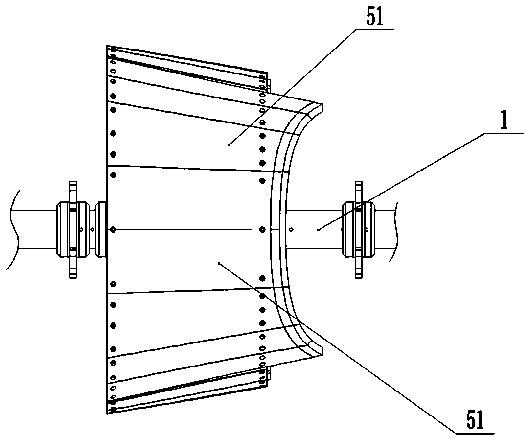
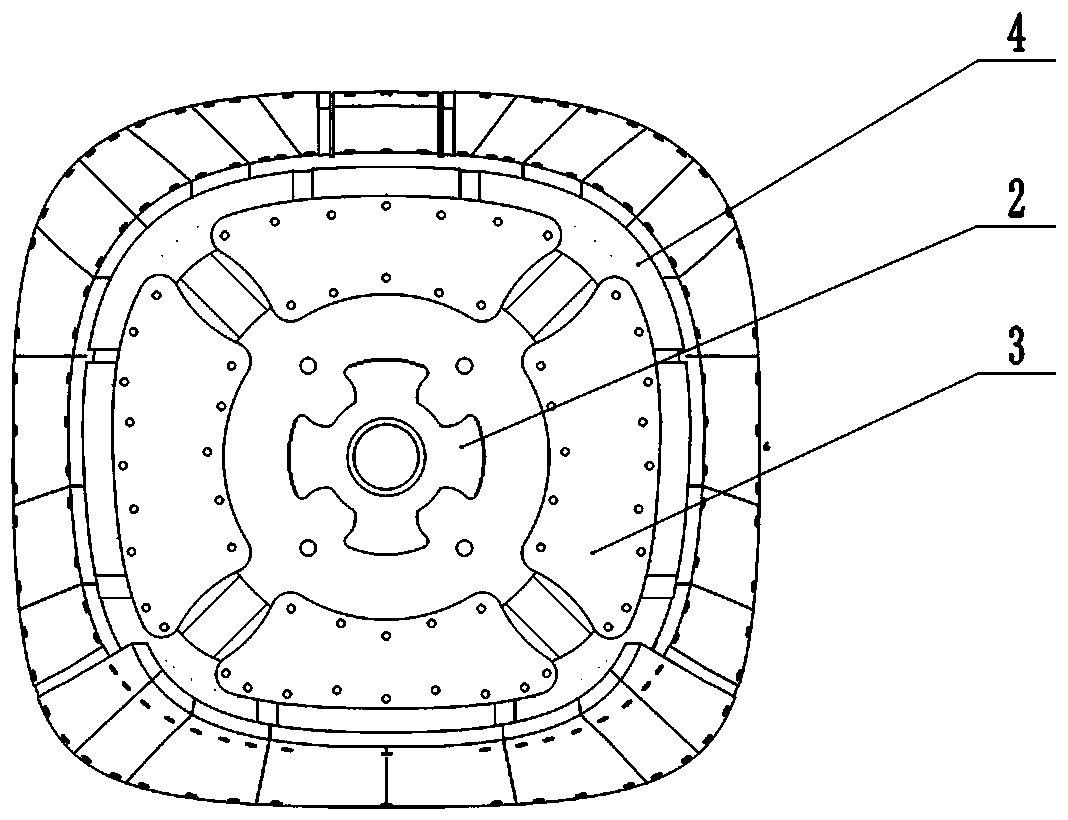
[0047] A combined molding die for small aircraft skins, comprising a mandrel 1, and at least two rotating plates 2 fixed on the mandrel 1, a transition plate connected to the turning plates 2 with quick-release pins, and the transition plate using The connection frame 4 connected by the quick release pin and the mold outer skin connected with the connection frame 4 bolts.

[0048] As a further solution: a driven gear 11 is fixed on the mandrel 1 .

[0049] As a further solution: the transition plate includes at least two sub-transition plates 3;

[0050] One end of the sub-transition plate 3 is connected with the quick release pin of the rotating plate 2, and the other end is connected with the quick release pin of the connecting frame 4.

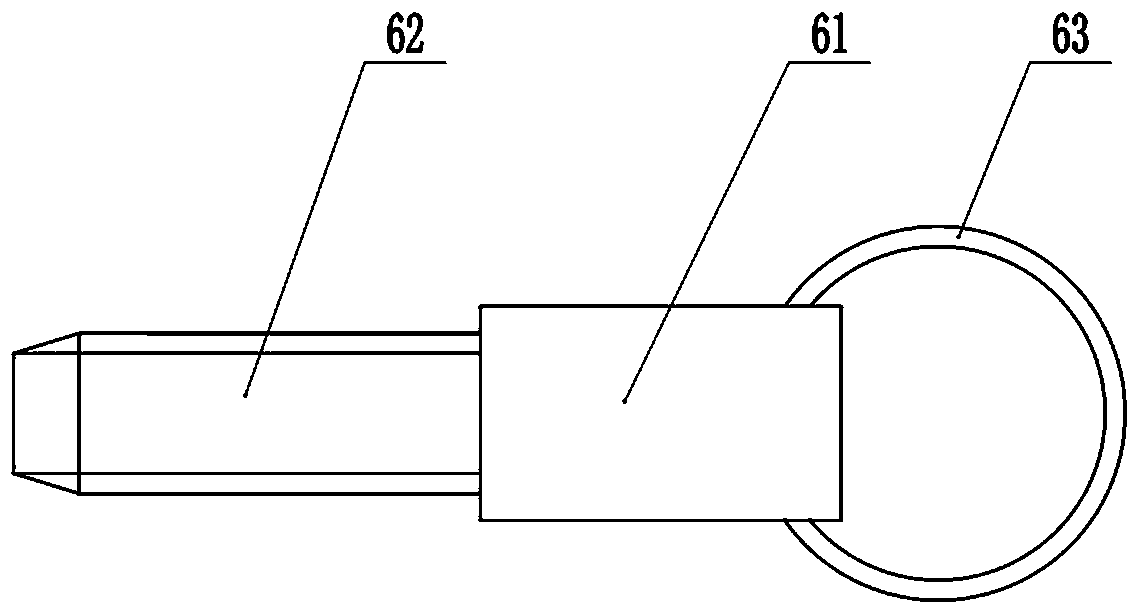
[0051] As a further solution: the quick release pin includes a connecting section 61, a stu...


PUM


Abstract

The invention discloses a small combined molding die for aircraft skin. The molding die comprises a central spindle, at least two rotating plates fixed to the central spindle, a filter plate connectedwith the rotating plates through quick-release pins, a connecting frame connected with the filter plate through a quick-release pin and die outer skin connected with the connecting frame through a bolt. All the components are connected through the quick-release pins, assembling and disassembling are convenient, and the needed aircraft skin production die can be rapidly assembled according to theproduction requirement. After manufacturing, disassembling work can be performed directly inside a product, scratches, crush injuries, internal cracks and the like caused by direct die release are greatly avoided, the using risk can be lowered, and the product quality is improved. All the components can be repeatedly and alternately used, the production cost of the aircraft skin is lowered, and economic benefits of a production plant are improved.

Description

technical field [0001] The invention relates to the field of aircraft skin production, in particular to a combined molding die for small aircraft skins. Background technique [0002] Aircraft skin refers to the three-dimensional component that surrounds the frame structure of the aircraft and is fixed on the frame with adhesives or rivets to form the aerodynamic shape of the aircraft. The skin structure composed of aircraft skin and skeleton has a large bearing capacity and rigidity, but its own weight is very light, and it plays the role of bearing and transmitting aerodynamic loads. After the skin is subjected to aerodynamic action, the force is transmitted to the connected fuselage and wing frame. The force is complex, and the skin is in direct contact with the outside world. Therefore, not only the skin material is required to have high strength and good plasticity, but also a smooth surface. It has high corrosion resistance. [0003] Early or low-speed small aircraft ...

Claims


Application Information

Patent Timeline
Patent Type & Authority Applications(China)
IPC IPC(8): B64F5/10B29C33/30B29C70/54
CPCB64F5/10B29C33/30B29C70/54Y02T50/40
Inventor 崔志华孙凤琴侯学佳李丁
Owner 石家庄飞机工业有限责任公司
Why Eureka
Try Eureka