Fiber bragg grating humidity sensor with non-grating areas being coated with polyimide

A technology of humidity sensor and optical fiber grating, which is applied in instruments, scientific instruments, and material analysis through optical means, etc., can solve the problems of complex packaging structure, poor hysteresis of sensors, and uneven edge warping of materials, etc. To achieve the effect of improving yield and comprehensive performance, broad application prospects, and improving yield

Pending Publication Date: 2018-07-06
濮阳光电产业技术研究院
View PDF9 Cites 6 Cited by
  • Summary
  • Abstract
  • Description
  • Claims
  • Application Information

AI Technical Summary

Problems solved by technology

Known humidity sensor (for example CN202869694U), its design method is that polyimide solution is directly coated on fiber grating grating region, through high-temperature thermosetting design, this method easily causes the fracture of fiber grating; Simultaneously fiber grating region directly Coating is easily affected by uneven force on the material and edge warpage, resulting in chirp phenomenon, which affects the practical monitoring of the sensor
In addition, the known humidity sensor (such as CN102393359A) proposes a structure in which a water-absorbing-swellable hydrogel material is combined with an optical fiber grating. Although the direct coating of the grating is avoided, the packaging structure is complicated, and the strain transfer efficiency is not high, resulting in low sensitivity. Moreover, the hysteresis of the sensor is not good, which affects the accurate detection of humidity by the sensor

Method used


Image

  • Fiber bragg grating humidity sensor with non-grating areas being coated with polyimide

Examples


Embodiment Construction

[0017] The structure of the fiber grating humidity sensor of the present invention will be described in further detail below with reference to the accompanying drawings and specific implementations.

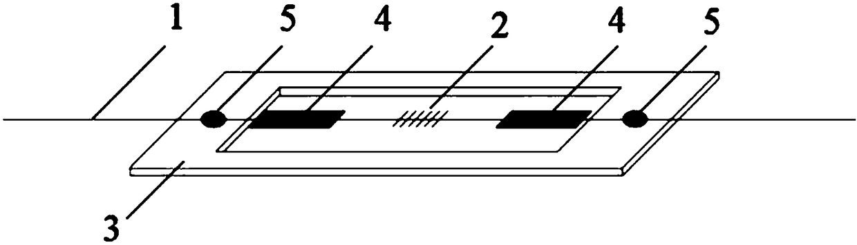
[0018] like figure 1 Shown is a schematic structural diagram of a fiber grating humidity sensor coated with polyimide in a non-grid area, including a single-mode optical fiber 1 and a hollow substrate 3, the single-mode optical fiber 1 is fixed on the hollow substrate 3, and the single-mode optical fiber 1. It is fixed on the hollow substrate 3 with UV ultraviolet glue 5, and the fiber Bragg grating 2 is laser engraved on the single-mode fiber 1 of the hollow part in the middle of the hollow substrate 3. The non-grid areas at both ends of the fiber Bragg grating 2 are respectively covered with polyamide. The imine film 4 forms a structure of "polyimide film-fiber grating-polyimide film". The "polyimide film-fiber grating-polyimide film" structure is pre-stressed first, so that t...


PUM

PropertyMeasurementUnit
thicknessaaaaaaaaaa
thermal decomposition temperatureaaaaaaaaaa
water absorptionaaaaaaaaaa

Abstract

The invention belongs to the field of an optical fiber sensing technology, and particularly relates to a fiber bragg grating humidity sensor with non-grating areas being coated with polyimide. The fiber bragg grating humidity sensor with the non-grating areas being coated with the polyimide comprises a monomode optical fiber and a hollow-out base plate, wherein the monomode optical fiber is fixedonto the hollow-out base plate through a UV (Ultraviolet) adhesive; an optical fiber Bragg grating is laser-engraved on the monomode optical fiber at the middle hollow-out part on the hollow-out baseplate; polyimide films are respectively covered on the non-grating areas at two ends of the optical fiber Bragg grating so as to form a 'polyimide film-fiber Bragg grating-polyimide film' structure. The fiber bragg grating humidity sensor with the non-grating areas being coated with the polyimide provided by the invention has the advantages of simple structure, high measurement accuracy, good linearity, high temperature resistance, electromagnetic interference resistance and the like, can realize multi-point quasi-distributed sensing, and has a wide application prospect.

Description

technical field [0001] The invention belongs to the technical field of optical fiber sensing, in particular to a fiber grating humidity sensor coated with polyimide in a non-grid area. Background technique [0002] Humidity is an important physical parameter, and humidity measurement has a wide range of applications in industrial production, agriculture, medical treatment, meteorological analysis, and aerospace. The industry has strict requirements for humidity measurement, including the environmental adaptability, measurement range, response speed, measurement accuracy and other important indicators of the humidity sensor. At present, electrical humidity sensors are dominant in the market, including resistive, capacitive, etc. The advantages are high measurement accuracy, fast response speed, and easy signal control and processing. However, the long-term stability and interchangeability of the electrical humidity sensor are poor, and it cannot work normally in a strong ele...

Claims


Application Information

Patent Timeline
Patent Type & Authority Applications(China)
IPC IPC(8): G01N21/17
CPCG01N21/17
Inventor 陈龙飞李明张豪杰申晓月张飞鳞
Owner 濮阳光电产业技术研究院
Why Eureka
Try Eureka